NPort 5600-8-DT Quick Installation Guide Version 5.1, January 2020 Technical Support Contact Information www.moxa.com/support Moxa Americas: Toll-free: 1-888-669-2872 Tel: 1-714-528-6777 Fax: 1-714-528-6778 Moxa China (Shanghai office): Toll-free: 800-820-5036 Tel: +86-21-5258-9955 Fax: +86-21-5258-5505 Moxa Europe: Tel: +49-89-3 70 03 99-0 Fax: +49-89-3 70 03 99-99 Moxa Asia-Pacific: Tel: +886-2-8919-1230 Fax: +886-2-8919-1231 Moxa India: Tel: +91-80-4172-9088 Fax: +91-80-4132-1045 2020 Moxa Inc.
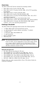
Overview The NPort 5600-8-DT Series includes the following models: • • • • • • • • NPort 5610-8-DT: 8 ports, RS-232, DB9 NPort 5610-8-DT-T: 8 ports, RS-232, DB9, -40 to 75°C operating temperature NPort 5610-8-DT-J: 8 ports, RS-232, RJ45 NPort 5650-8-DT: 8 ports, RS-232/422/485, DB9 NPort 5650-8-DT-T: 8 ports, RS-232/422/485, DB9, -40 to 75°C operating temperature NPort 5650-8-DT-J: 8 ports, RS-232/422/485, RJ45 NPort 5650I-8-DT: 8 ports, RS-232/422/485, DB9, optical isolation NPort 5650I-8-DT-T: 8 ports, R
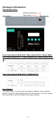
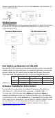
Hardware Introduction Top and Rear View Front View (NPort 5610-8-DT, NPort 5610-8-DT-T, NPort 56508-DT, NPort 5650-8-DT-T, NPort 5650I-8-DT, NPort 5650I-8-DTT) Front View (NPort 5610-8-DT-J, 5650-8-DT-J) Reset Button The reset button is used to load the factory defaults. Use a pointed object to hold the reset button down for five seconds. You may release the reset button when the Ready LED stops blinking.
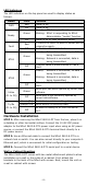
LED Indicators The LED indicators on the top panel are used to display status as follows: Name PWR Ready Color Red Off Green Off Fault Red Off Green ETH1 Off Green ETH2 Off InUse (P1 to P8) Tx/Rx (P1 to P8) Function Power is on. Power is off. Steady: NPort is operational Blinking: NPort is responding to NPort Administrator “Locate” function Power is off or fault condition exists. IP conflict or DHCP or BOOTP server did not respond properly. No fault condition detected.
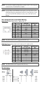
Screws should be less than 6.0 mm in head diameter, and less than 3.5 mm in shaft diameter. DIN Rail Mounting DIN-rail attachments can be purchased separately to attach the product to a DIN-rail. The DIN-rail attachments should be oriented with the metal springs on top. Standard Attachment DK-35A Attachment Pull High/Low Resistors for RS-485 Use the set of DIP switches on the bottom panel to set the pull high/low resistor values for each serial port.
NOTE For security-related configuration, please refer to the manual’s Cybersecurity Considerations chapter. NOTE For the NPort with DB Male serial ports, you may refer to the DB9 Male Ports pin assignment section to loop back pin 2 and pin 3 for the RS-232 interface to carry out a self test on the device.
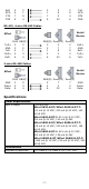
RxD DCD CTS DTR 5 6 7 8 2 1 8 4 3 1 7 6 3 8 5 20 2 8 4 6 TxD DCD RTS DSR RS-422, 4-wire RS-485 Cables Serial Device NPort TxD+ GND TxDRxD+ RxD- RJ45 DB9(F) 2 2 3 5 4 1 5 3 6 4 DB9(M) DB25(M) DB25(F) 3 3 2 5 7 7 1 8 8 2 2 3 6 20 6 RxD+ GND RxDTxD+ TxD- 2-wire RS-485 Cables Serial Device NPort GND Data+ Data- RJ45 DB9(F) 3 5 5 3 6 4 DB9(M) DB25(M) DB25(F) 5 7 7 GND 2 2 3 Data+ 6 20 6 Data- Specifications Power Requirements Input Voltage Certifications Regulatory Approvals 12 to 48 VDC NPor