
User Manual

- 3 -
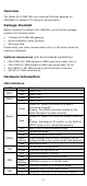
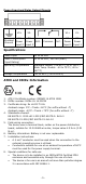
LED
Color
Function
Ethernet
Amber
Steady: 10Mbps, no data is transmitting
Blinking: 10Mbps, data is transmitting
Green
Steady: 100Mbps, no data is transmitting
Blinking: 100Mbps, data is transmitting
Off
Ethernet cable is disconnected
Reset Button
The reset button is used to load factory defaults. Use a pointed object
such as a straightened paper clip to hold the reset button down for five
seconds. Release the reset button when the Ready LED stops blinking.
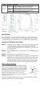
Hardware Installation Procedure
STEP 1:
Connect the power adapter. Connect the 12-48 VDC power line
or DIN
-rail power supply with the MGate 5101-PBM-MN
device’s terminal block.
Make sure the adapter is connected to
an earthed socket.
STEP 2:
Use a PROFIBUS cable to connect the unit to a PROFIBUS slave
device.
STEP 3:
Connect the unit to the Modbus TCP device.
STEP 4
:
The
MGate 5101-PBM-MN series is designed to be
attached to
a DIN
rail or mounted on a wall. For DIN-rail
mounting, push
down the spring and properly attach it to the
DIN-rail until
it
“snaps” into place. For wall
mounting, install the wall-mount
kit (optional) first
and then screw the device onto the wall.
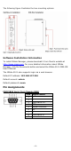
Wall or Cabinet Mounting
Two metal plates are provided for mounting the
unit on a wall or inside a cabinet. Attach the plates
to the unit’s rear panel with screws. With the plates
attached, use screws to mount the unit on a wall.
The heads of the screws should be 5 to 7 mm in
diameter, the shafts should be 3 to 4 mm in
diameter, and the length of the screws should be
more than 10.5 mm.
For each screw, the head should be 6 mm or less in diameter, and the
shaft should be 3.5 mm or less in diameter.