
Installation Guide
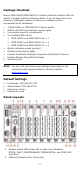
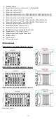
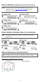
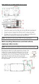
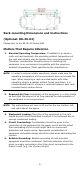
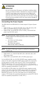
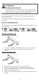
Table Of Contents
- MDS-G4000/MDS-G4000-L3 Series Quick Installation Guide
- Package Checklist
- Default Settings
- Panel Layouts
- Dimensions
- Ethernet Modules (Hardware Rev.2.0.0 and above)
- Power Modules (Hardware Rev.2.1.0 and above)
- DIN-rail Dimensions and Instructions
- Wall-mounting Dimensions and Instructions (Optional: WK-112-01)
- Rack-mounting Dimensions and Instructions (Optional: RK-3U-02)
- Matters That Require Attention
- Connecting the Power Inputs
- Power Terminal Blocks
- PoE Power Terminal Blocks
- Wiring the Relay Contact
- Digital Input/Output
- Installing and Removing the Ethernet Modules
- Installing and Removing the Power Modules
- Grounding the Moxa Industrial DIN-rail Switch
- RS-232 with RJ45 Interface Console Connection
- USB Connection
- Reset to Factory Default Settings
- LED Indicators
- Specifications
- Supported SFP Modules
- Restricted Access Locations
- Special Conditions of Use
- Hazardous Location Usage Terms

- 9 -
PoE Power Terminal Blocks
1. Remove 8 to 9 mm of the DC wires’ protective cover.
2. Use a tool to push the spring mechanism inwards to open it.
3. Insert the negative/positive (-/+) DC wires into the terminals.
4. Release the spring mechanism.
5. Insert the terminal block connector prongs into the terminal block
receptor.
NOTE
In order to have higher levels of protection against surge, it is
suggested to install a surge protector in front of the power
input
of the PoE powered device so that it is suitable for use in
IEC 61850 conditions.
NOTE
When wiring the power input, we
suggest using the cable type
-
AWG (American Wire Gauge) 1
6-20 (1.31-0.519 mm
2
) and the
corresponding pin type cable terminals. The rated temperature
of wiring should be at least 105°C.
NOTE
When wiring the
PoE power input, we suggest using the cable
ty
pe - AWG (American Wire Gauge) 16 (1.31 mm
2
) and the
corresponding pin type cable terminals. The rated temperature
of wiring should be at least 105°C.
NOTE
When two power units are installed on the switch, both power
units will be activated
simultaneously, which will enable power
redundancy.
NOTE
The reverse power input connection will not activate the device
or PoE input
. In addition, the PoE will only activate when the
external power supply is installed on the same power unit.
Wiring the Relay Contact
Each power module has one relay output that can provide two types of
relay output. Refer to the table below for detailed information.
The relay contact is used to detect user-configured events. Two wires
are attached to the relay pins with normally close and normally open
options.
1. Remove 8 to 9 mm of the DC wires’ protective cover.
2. Use a tool to push the spring mechanism inwards to open it.
3. Insert the wires into the terminals.
4. Release the spring mechanism.
5. Insert the terminal block connector prongs into the terminal block
receptor.