
Installation Guide
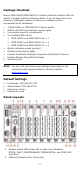
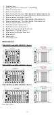
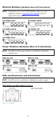
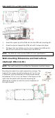
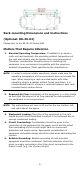
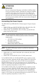
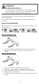
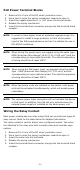
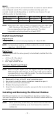
Table Of Contents
- MDS-G4000/MDS-G4000-L3 Series Quick Installation Guide
- Package Checklist
- Default Settings
- Panel Layouts
- Dimensions
- Ethernet Modules (Hardware Rev.2.0.0 and above)
- Power Modules (Hardware Rev.2.1.0 and above)
- DIN-rail Dimensions and Instructions
- Wall-mounting Dimensions and Instructions (Optional: WK-112-01)
- Rack-mounting Dimensions and Instructions (Optional: RK-3U-02)
- Matters That Require Attention
- Connecting the Power Inputs
- Power Terminal Blocks
- PoE Power Terminal Blocks
- Wiring the Relay Contact
- Digital Input/Output
- Installing and Removing the Ethernet Modules
- Installing and Removing the Power Modules
- Grounding the Moxa Industrial DIN-rail Switch
- RS-232 with RJ45 Interface Console Connection
- USB Connection
- Reset to Factory Default Settings
- LED Indicators
- Specifications
- Supported SFP Modules
- Restricted Access Locations
- Special Conditions of Use
- Hazardous Location Usage Terms

- 8 -
ATTENTION
F
or Hazardous Location Use
The
PoE capacity of the PWR-LV-P48 is only certified for use in
h
azardous locations up to a maximum power budget of 369.6
W and a maximum output of up to 15.4 W per port.
For the PWR-HV-NP, the 110/220 VAC/VDC power supplies provide
power to the switch.
For the PWR-LV-NP, the 24/48 VDC power supplies provide power to
the switch.
Power Terminal Blocks
The connection for power input and PoE external power supply is on the
power modules.
PWR-HV-P48/PWR-HV-NP
1. Insert the neutral/line (L/N/Ground) AC wires into the terminals.
2. Insert the terminal block connector into the terminal block
receptor.
PWR-LV-P48/PWR-LV-NP
1. Remove 8 to 9 mm of the DC wires’ protective cover.
2. Use a tool to push the spring mechanism inwards to open it.
3. Insert the negative/positive (-/+) DC wires into the terminals.
4. Release the spring mechanism.
5. Insert the terminal block connector prongs into the terminal block
receptor.