
Installation Guide
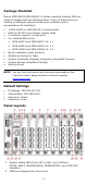
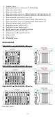
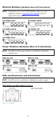
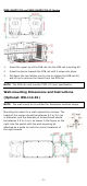
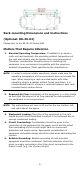
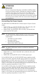
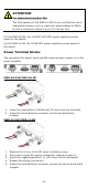
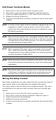
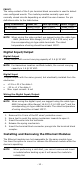
Table Of Contents
- MDS-G4000/MDS-G4000-L3 Series Quick Installation Guide
- Package Checklist
- Default Settings
- Panel Layouts
- Dimensions
- Ethernet Modules (Hardware Rev.2.0.0 and above)
- Power Modules (Hardware Rev.2.1.0 and above)
- DIN-rail Dimensions and Instructions
- Wall-mounting Dimensions and Instructions (Optional: WK-112-01)
- Rack-mounting Dimensions and Instructions (Optional: RK-3U-02)
- Matters That Require Attention
- Connecting the Power Inputs
- Power Terminal Blocks
- PoE Power Terminal Blocks
- Wiring the Relay Contact
- Digital Input/Output
- Installing and Removing the Ethernet Modules
- Installing and Removing the Power Modules
- Grounding the Moxa Industrial DIN-rail Switch
- RS-232 with RJ45 Interface Console Connection
- USB Connection
- Reset to Factory Default Settings
- LED Indicators
- Specifications
- Supported SFP Modules
- Restricted Access Locations
- Special Conditions of Use
- Hazardous Location Usage Terms

- 6 -
Rack-mounting Dimensions and Instructions
(Optional: RK-3U-02)
Please refer to the RK-3U-02 Series QIG.
Matters That Require Attention
1. Elevated Operating Temperature: If installed in a closed or
multi-unit rack assembly, the operating ambient temperature of
the rack environment may be greater than room temperature.
Therefore, consideration should be given to installing the
equipment in an environment compatible with the maximum
ambient temperature (Tma) specified by the manufacturer.
NOTE
In order to
ensure reliable operations, please make sure the
operating temp
erature of the environment does not exceed the
spec. When mounting a rack
-mounted switch with other
operating units in a cabinet without forced ventilation, it is
recommended that 1U of space
is reserved between each rack-
mounted switch and/or device.
2. Required Air Flow: Installation of the equipment in a rack should
be such that the amount of air flow required for safe operation of
the equipment is not compromised.
NOTE
The optimal keep-out zone is 50 mm for the top, bottom, left,
and right side of the device.
3. Mechanical Loading: Mounting of the equipment in the rack
should be such that a hazardous condition is not achieved due to
uneven mechanical loading.
4. Circuit Overloading: Consideration should be given to the
connection of the equipment to the supply circuit and the effect
that overloading of the circuits might have on overcurrent
protection and supply wiring. Appropriate consideration of
equipment nameplate ratings should be used when addressing this
concern.
5. Reliable Grounding: Reliable grounding of rack-mounted
equipment should be maintained. Particular attention should be
given to supply connections other than direct connections to the
branch circuit (e.g. use of power strips).