
Installation Guide
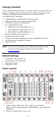
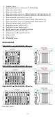
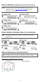
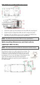
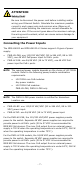
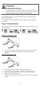
Table Of Contents
- MDS-G4000/MDS-G4000-L3 Series Quick Installation Guide
- Package Checklist
- Default Settings
- Panel Layouts
- Dimensions
- Ethernet Modules (Hardware Rev.2.0.0 and above)
- Power Modules (Hardware Rev.2.1.0 and above)
- DIN-rail Dimensions and Instructions
- Wall-mounting Dimensions and Instructions (Optional: WK-112-01)
- Rack-mounting Dimensions and Instructions (Optional: RK-3U-02)
- Matters That Require Attention
- Connecting the Power Inputs
- Power Terminal Blocks
- PoE Power Terminal Blocks
- Wiring the Relay Contact
- Digital Input/Output
- Installing and Removing the Ethernet Modules
- Installing and Removing the Power Modules
- Grounding the Moxa Industrial DIN-rail Switch
- RS-232 with RJ45 Interface Console Connection
- USB Connection
- Reset to Factory Default Settings
- LED Indicators
- Specifications
- Supported SFP Modules
- Restricted Access Locations
- Special Conditions of Use
- Hazardous Location Usage Terms

- 5 -
MDS-G4020/28 and MDS-G4020/28-L3 Series
1. Insert the upper lip of the DIN rail into the DIN-rail mounting kit.
2. Press the device towards the DIN rail until it snaps into place.
3. Pull down the two latches one by one to release the DIN-rail kit
and lift up to remove the device from the DIN rail.
NOTE
The DIN rail must use the TS35 (15 mm) specification.
Wall-mounting Dimensions and Instructions
(Optional: WK-112-01)
NOTE
The wall-mount kit is certified for Hazardous Location usage.
Mounting the switch to a wall requires
four
screws. The
heads of the screws should be between 6.0 to
9.0 mm
in diameter, and the diameter of screw thread should
be between 3.5 to 4 mm, as shown in the figure on the
right
. Use the switch with the wall-mounting kit
attached as a guide to mark the correct locations of
the eight screws.