
Installation Guide
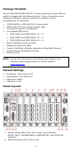
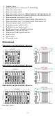
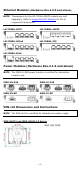
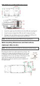
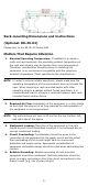
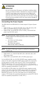
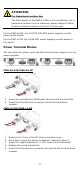
Table Of Contents
- MDS-G4000/MDS-G4000-L3 Series Quick Installation Guide
- Package Checklist
- Default Settings
- Panel Layouts
- Dimensions
- Ethernet Modules (Hardware Rev.2.0.0 and above)
- Power Modules (Hardware Rev.2.1.0 and above)
- DIN-rail Dimensions and Instructions
- Wall-mounting Dimensions and Instructions (Optional: WK-112-01)
- Rack-mounting Dimensions and Instructions (Optional: RK-3U-02)
- Matters That Require Attention
- Connecting the Power Inputs
- Power Terminal Blocks
- PoE Power Terminal Blocks
- Wiring the Relay Contact
- Digital Input/Output
- Installing and Removing the Ethernet Modules
- Installing and Removing the Power Modules
- Grounding the Moxa Industrial DIN-rail Switch
- RS-232 with RJ45 Interface Console Connection
- USB Connection
- Reset to Factory Default Settings
- LED Indicators
- Specifications
- Supported SFP Modules
- Restricted Access Locations
- Special Conditions of Use
- Hazardous Location Usage Terms

- 4 -
Ethernet Modules (Hardware Rev.2.0.0 and above)
NOTE
Transceivers for the LM-7000H-4GSFP module are sold
separately. Refer to
Supported SFP Modules for list of
supported transceivers.
LM-7000H-4GTX
LM-7000H-4GSFP
LM-7000H-4GPoE
LM-7000H-4TX
LM-7000H-4PoE
Power Modules (Hardware Rev.2.1.0 and above)
NOTE
The PWR-LV-P48 power module is certified for Hazardous
Location use.
PWR-HV-P48
PWR-LV-P48
PWR-HV-NP
PWR-LV-NP
DIN-rail Dimensions and Instructions
NOTE
The DIN rail kit is certified for Hazardous Location usage.
MDS-G4012 and MDS-G4012-L3 Series