
Installation Guide
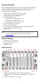
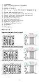
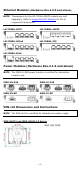
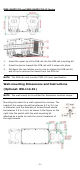
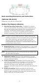
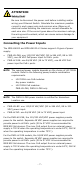
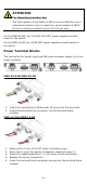
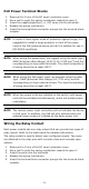
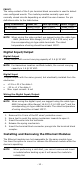
Table Of Contents
- MDS-G4000/MDS-G4000-L3 Series Quick Installation Guide
- Package Checklist
- Default Settings
- Panel Layouts
- Dimensions
- Ethernet Modules (Hardware Rev.2.0.0 and above)
- Power Modules (Hardware Rev.2.1.0 and above)
- DIN-rail Dimensions and Instructions
- Wall-mounting Dimensions and Instructions (Optional: WK-112-01)
- Rack-mounting Dimensions and Instructions (Optional: RK-3U-02)
- Matters That Require Attention
- Connecting the Power Inputs
- Power Terminal Blocks
- PoE Power Terminal Blocks
- Wiring the Relay Contact
- Digital Input/Output
- Installing and Removing the Ethernet Modules
- Installing and Removing the Power Modules
- Grounding the Moxa Industrial DIN-rail Switch
- RS-232 with RJ45 Interface Console Connection
- USB Connection
- Reset to Factory Default Settings
- LED Indicators
- Specifications
- Supported SFP Modules
- Restricted Access Locations
- Special Conditions of Use
- Hazardous Location Usage Terms

- 3 -
3. Module status
4. Switch and Control module slot 1 (Embedded)
5. Ethernet module slot 2
6. Ethernet module slot 3
7. Ethernet module slot 4 (For MDS-G4020/28, MDS-G4020/28-L3)
8. Ethernet module slot 5 (For MDS-G4020/28, MDS-G4020/28-L3)
9. External power input status from EPS
10. Ethernet module slot 6 (For MDS-G4028, MDS-G4028-L3)
11. Ethernet module slot 7 (For MDS-G4028, MDS-G4028-L3)
12. External power supply input for PoE
13. Redundant power module slot 1
14. Redundant power module slot 2
15. RS232 console port with RJ45 interface
16. Reset button (Pin hole 0.9 mm)
17. Relay output and Digital Input port
18. Relay output
19. Power input
20. Grounding screw
Dimensions
MDS-G4012 and MDS-G4012-L3 Series
MDS-G4020 and MDS-G4020-L3 Series
MDS-G4028 and MDS-G4028-L3 Series
Unit: mm (inch)