
Installation Guide
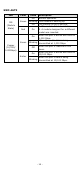
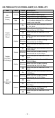
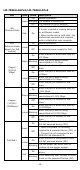
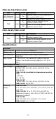
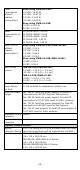
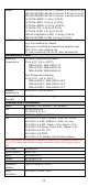
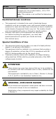
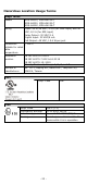
Table Of Contents
- MDS-G4000/MDS-G4000-L3 Series Quick Installation Guide
- Package Checklist
- Default Settings
- Panel Layouts
- Dimensions
- Ethernet Modules (Hardware Rev.2.0.0 and above)
- Power Modules (Hardware Rev.2.1.0 and above)
- DIN-rail Dimensions and Instructions
- Wall-mounting Dimensions and Instructions (Optional: WK-112-01)
- Rack-mounting Dimensions and Instructions (Optional: RK-3U-02)
- Matters That Require Attention
- Connecting the Power Inputs
- Power Terminal Blocks
- PoE Power Terminal Blocks
- Wiring the Relay Contact
- Digital Input/Output
- Installing and Removing the Ethernet Modules
- Installing and Removing the Power Modules
- Grounding the Moxa Industrial DIN-rail Switch
- RS-232 with RJ45 Interface Console Connection
- USB Connection
- Reset to Factory Default Settings
- LED Indicators
- Specifications
- Supported SFP Modules
- Restricted Access Locations
- Special Conditions of Use
- Hazardous Location Usage Terms

- 23 -
Hazardous Location Usage Terms
Usage Terms
Models MDS-G4012, MDS-G4012-T
MDS-G4020, MDS-G4020-T
MDS-G4028, MDS-G4028-T
Rating
Input: 24 to 48 VDC, 3.3 A (for PWR input) and 48
VDC, 8.2 A (for EPS input)
Relay Output: 30 VDC/1 A
Digital Input: 30 VDC/8 mA
PoE Output: 48 VDC, 15.4 W per port
Conductors
suitable for rated
cable
temperature
≧
105°C
Hazardous
Location
EN IEC 60079-0:2018
EN IEC 60079-7:2015+A1:2018
EN IEC 60079-15: 2019
Class I, Division 2, Groups A, B, C, and D
Address of
manufacturer
No. 1111, Heping Rd., Bade Dist., Taoyuan City
334004, Taiwan
CID2
Temp. Code T3B
ATEX
Temp. Code
165°C (T3)
Certification Number
UL 20 ATEX 2415X
Protection type code
Ex ec nC IIC 165°C (T3) Gc
Warning
Do not open or disassemble the
device while it is in operation