
Installation Guide
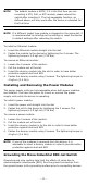
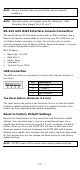
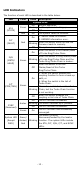
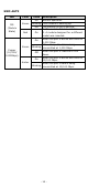
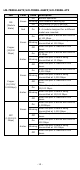
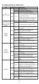
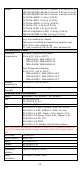
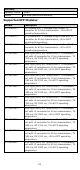
Table Of Contents
- MDS-G4000/MDS-G4000-L3 Series Quick Installation Guide
- Package Checklist
- Default Settings
- Panel Layouts
- Dimensions
- Ethernet Modules (Hardware Rev.2.0.0 and above)
- Power Modules (Hardware Rev.2.1.0 and above)
- DIN-rail Dimensions and Instructions
- Wall-mounting Dimensions and Instructions (Optional: WK-112-01)
- Rack-mounting Dimensions and Instructions (Optional: RK-3U-02)
- Matters That Require Attention
- Connecting the Power Inputs
- Power Terminal Blocks
- PoE Power Terminal Blocks
- Wiring the Relay Contact
- Digital Input/Output
- Installing and Removing the Ethernet Modules
- Installing and Removing the Power Modules
- Grounding the Moxa Industrial DIN-rail Switch
- RS-232 with RJ45 Interface Console Connection
- USB Connection
- Reset to Factory Default Settings
- LED Indicators
- Specifications
- Supported SFP Modules
- Restricted Access Locations
- Special Conditions of Use
- Hazardous Location Usage Terms

- 13 -
LED Indicators
The function of each LED is described in the table below.
LED
Color
State
Description
System LEDs
STA
(STATE)
Green
On
Normal operation.
Blinking
1. The system is booting up.
Off
N/A
Red
On
The system failed to initialize.
FLT
(FAULT)
Red
On
1. Switch failed to initialize.
2. EEPROM information error.
Blinking
When the switch boots up and the
firmware loads to memory.
Off
The system is operating normally.
M/H
(MSTR/
HEAD)
Green
On
When the switch is the Master/Head
of Turbo Ring/Turbo Chain.
Blinking
When the switch is Ring Master/Head
of Turbo Ring/Turbo Chain and the
Turbo Ring/Turbo Chain is broken.
Off
When the switch is not the
Master/Head of this Turbo
Ring/Turbo Chain.
C/T
(CPRL/TAIL)
Green
On
1. When the switch enables the
coupling function to form a back-up
path, or
2. When the switch is the tail of
Turbo Chain.
Blinking
This is the switch that enables Turbo
Chain, but the Turbo Chain function
is not working.
Off
When the switch disables the
coupling or tail role of Turbo Chain.
SYNC
(Reserved)
Amber
On
The PTP function is enabled.
Blinking
The switch receives sync packets.
Off
The PTP function is disabled.
Green On
The PTP function has successfully
converged.
System LED
(Except
PWR)
Green/
Amber/
Red
Blinking
The switch is being
discovered/located by the locator
function. The system LEDs include
the STA, FLT, M/H, C/T, and SYNC
LEDs.