
Installation Guide
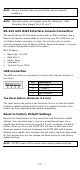
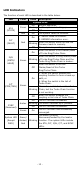
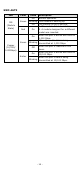
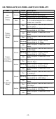
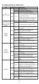
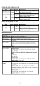
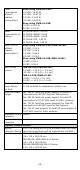
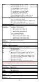
Table Of Contents
- MDS-G4000/MDS-G4000-L3 Series Quick Installation Guide
- Package Checklist
- Default Settings
- Panel Layouts
- Dimensions
- Ethernet Modules (Hardware Rev.2.0.0 and above)
- Power Modules (Hardware Rev.2.1.0 and above)
- DIN-rail Dimensions and Instructions
- Wall-mounting Dimensions and Instructions (Optional: WK-112-01)
- Rack-mounting Dimensions and Instructions (Optional: RK-3U-02)
- Matters That Require Attention
- Connecting the Power Inputs
- Power Terminal Blocks
- PoE Power Terminal Blocks
- Wiring the Relay Contact
- Digital Input/Output
- Installing and Removing the Ethernet Modules
- Installing and Removing the Power Modules
- Grounding the Moxa Industrial DIN-rail Switch
- RS-232 with RJ45 Interface Console Connection
- USB Connection
- Reset to Factory Default Settings
- LED Indicators
- Specifications
- Supported SFP Modules
- Restricted Access Locations
- Special Conditions of Use
- Hazardous Location Usage Terms

- 11 -
NOTE
The default module is 4GTX, if it is the first time you are
mounting a 4TX, PoE, or SFP module, please reboot the
switch after inserting it. The hot-swappable function, as
defined above, will only work after the device is rebooted for
the first time.
NOTE
If a different model type module is changed on the same slot, it
is recommend
ed to reconfigure the settings or reset the device
to default settings after rebooting the switch.
To install an Ethernet module:
1. Insert the Ethernet module straight into the slot.
2. Fasten the module to the device by tightening the 2 screws. The
tightening torque is 3.5 kgf-cm (0.35 Nm).
To remove an Ethernet module:
1. Loosen the 2 screws of the module.
2. Pull the module out of the slot.
3. Insert the dummy module into the slot in order to have better
protection against dust and EMI.
4. Fasten the dummy module using 2 screws. The tightening torque is
4 kgf-cm (0.4 Nm).
Installing and Removing the Power Modules
The power supply units are hot-swappable when both power modules
are installed. You have the option to mount or remove the power
supply units while the device is operating.
To install a power module:
1. Insert the power unit straight into the slot
2. Fasten the unit to the device by tightening the 2 screws. The
tightening torque is 3.5 kgf-cm (0.35 Nm)
To remove a power module:
1. Loosen the 2 screws of the module
2. Pull the module out of the slot
3. Insert the dummy module in to the slot in order to have better
protection against dust and EMI.
4. Fasten the dummy module using 2 screws. The tightening torque is
4 kgf-cm (0.4 Nm)
NOTE
If one of the modules is removed from the device, it is
advisable to insert a dummy module in order to provide better
protection against dust and EMI.
Grounding the Moxa Industrial DIN-rail Switch
Grounding and wire routing help limit the effects of noise due to
electromagnetic interference (EMI). Run the ground connection from
the ground screw to the grounding surface prior to connecting devices.