
Installation Guide
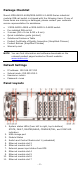
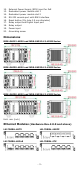
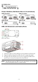
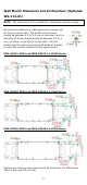
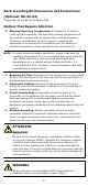
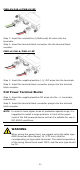
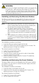
Table Of Contents
- MDS-G4000-4XGS/ MDS-G4000-L3-4XGS Series Quick Installation Guide
- Package Checklist
- Default Settings
- Panel Layouts
- Dimensions
- Ethernet Modules (Hardware Rev.2.0.0 and above)
- Power Modules (Hardware Rev.2.1.0 and above)
- DIN-rail Dimension and Instructions
- Wall Mount Dimension and Instructions (Optional: WK-112-01)
- Rack-mounting Kit Dimensions and Instructions (Optional: RK-3U-02)
- Matters That Require Attention
- Connecting the Power Inputs
- Power Terminal Blocks
- PoE Power Terminal Blocks
- Wiring the Relay Contact
- Digital Input/Output
- Installing and Removing the Ethernet Modules
- Installing and Removing the Power Modules
- Grounding the Moxa Industrial DIN-rail Switch
- RS-232 with RJ45 Interface Console Connection
- USB Storage Connection
- Resetting to Factory Default Settings
- LED Indicators
- Specifications
- Restricted Access Locations

- 9 -
NOTE
When two power units are installed on the MDS-G4000-
4XGS/MDS
-G4000-L3-4XGS Series
switch, both power units will
be activated simultaneously, which will enab
le power
redundancy.
NOTE
The reverse power input connection will not activate the device
or PoE input. In addition, the PoE will only activate when the
external power supply is installed on the same power unit.
Wiring the Relay Contact
Each power module has one relay output that can provide two types of
relay output. Refer to the table below for detailed information.
The relay contact is used to detect user-configured events. Two wires
are attached to the relay pins with normally close and normally open
options.
FAULT: The relay contact of the 3-pin terminal block connector is used
to detect user-configured events. The module provides normally open
and normally closed circuits depending on what the user chooses. For
pin definitions, refer to the table below.
Relay Connection
Power Off
Boot up Ready
Event Trigger
NO and COM
Closed Circuit
Open Circuit
Closed Circuit
NC and COM
Open Circuit
Closed Circuit
Open Circuit
WARNING
When wiring the relay contact, we suggest using the cable type
-
AWG (American Wire Gauge) 16-21 (1.31-0.412 mm
2
) and
the corresponding pin type
cable terminals. The rated
temperature of the wiring should be at least 105°C
and the wire
type should be CU.
Digital Input/Output
Digital Output
1 relay output with a current carrying capacity of 2 A @ 30 VDC.
Digital Input
1 digital output with the same ground, but electrically isolated from the
electronics.
• +13 to +30 V for state 1
• -30 to +1 V for state 0
• Max. input current: 8 mA