
Installation Guide
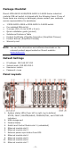
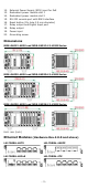
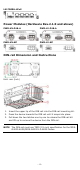
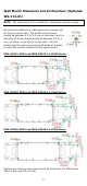
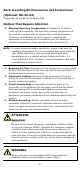
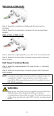
Table Of Contents
- MDS-G4000-4XGS/ MDS-G4000-L3-4XGS Series Quick Installation Guide
- Package Checklist
- Default Settings
- Panel Layouts
- Dimensions
- Ethernet Modules (Hardware Rev.2.0.0 and above)
- Power Modules (Hardware Rev.2.1.0 and above)
- DIN-rail Dimension and Instructions
- Wall Mount Dimension and Instructions (Optional: WK-112-01)
- Rack-mounting Kit Dimensions and Instructions (Optional: RK-3U-02)
- Matters That Require Attention
- Connecting the Power Inputs
- Power Terminal Blocks
- PoE Power Terminal Blocks
- Wiring the Relay Contact
- Digital Input/Output
- Installing and Removing the Ethernet Modules
- Installing and Removing the Power Modules
- Grounding the Moxa Industrial DIN-rail Switch
- RS-232 with RJ45 Interface Console Connection
- USB Storage Connection
- Resetting to Factory Default Settings
- LED Indicators
- Specifications
- Restricted Access Locations

- 8 -
PWR-HV-P48-A/PWR-HV-NP
Step 1: Insert the neutral/line (L/N/Ground) AC wires into the
terminals.
Step 2: Insert the terminal block connector into the terminal block
receptor.
PWR-LV-P48-A/PWR-LV-NP
Step 1: Insert the negative/positive (-/+) DC wires into the terminals.
Step 2: Insert the terminal block connector prongs into the terminal
block receptor.
PoE Power Terminal Blocks
Step 1: Insert the negative/positive DC wires into the -/+ terminals,
respectively.
Step 2: Insert the terminal block connector prongs into the terminal
block receptor.
NOTE
In order to have higher levels of protection against surge, it is
suggested to install
a surge protector in front of the power
input of the PoE powered device so that it is suitable for use in
IEC 61850 conditions.
WARNING
When wiring the power input, we suggest using the cable type -
AWG
(American Wire Gauge) 16 (1.31 mm
2
) and the
corresponding pin type cable terminals. The rated temperature
of the wiring should be at least 105°C and the wire type should
be CU.