
Installation Guide
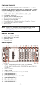
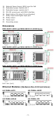
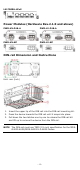
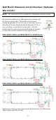
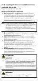
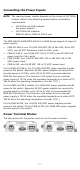
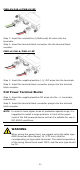
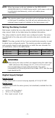
Table Of Contents
- MDS-G4000-4XGS/ MDS-G4000-L3-4XGS Series Quick Installation Guide
- Package Checklist
- Default Settings
- Panel Layouts
- Dimensions
- Ethernet Modules (Hardware Rev.2.0.0 and above)
- Power Modules (Hardware Rev.2.1.0 and above)
- DIN-rail Dimension and Instructions
- Wall Mount Dimension and Instructions (Optional: WK-112-01)
- Rack-mounting Kit Dimensions and Instructions (Optional: RK-3U-02)
- Matters That Require Attention
- Connecting the Power Inputs
- Power Terminal Blocks
- PoE Power Terminal Blocks
- Wiring the Relay Contact
- Digital Input/Output
- Installing and Removing the Ethernet Modules
- Installing and Removing the Power Modules
- Grounding the Moxa Industrial DIN-rail Switch
- RS-232 with RJ45 Interface Console Connection
- USB Storage Connection
- Resetting to Factory Default Settings
- LED Indicators
- Specifications
- Restricted Access Locations

- 5 -
Wall Mount Dimension and Instructions (Optional:
WK-112-01)
NOTE
The wall-mount kit is certified for Hazardous Location usage.
Mounting the switch to a wall requires four screws per
kit
(there are two kits). The heads of the screws
should be between 6.0 to 9.0 mm in diameter, and the
diameter of screw thread should be between 3.5 to 4
mm, as shown in the figure on the right. Use the
switch with the wall
-mounting kit attached as a guide
to mark the correct locations of the eight screws.
MDS-G4012-4XGS and MDS-G4012-L3-4XGS Series
MDS-G4020-4XGS and MDS-G4020-L3-4XGS Series
MDS-G4028-4XGS and MDS-G4028-L3-4XGS Series
Please note, there are two wall-mount kit screws for the MDS Series
(M4 x 8 mm and M3 x 6 mm).