
Installation Guide
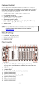
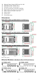
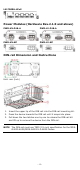
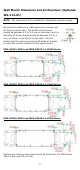
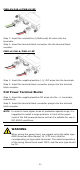
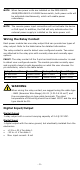
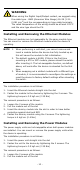
Table Of Contents
- MDS-G4000-4XGS/ MDS-G4000-L3-4XGS Series Quick Installation Guide
- Package Checklist
- Default Settings
- Panel Layouts
- Dimensions
- Ethernet Modules (Hardware Rev.2.0.0 and above)
- Power Modules (Hardware Rev.2.1.0 and above)
- DIN-rail Dimension and Instructions
- Wall Mount Dimension and Instructions (Optional: WK-112-01)
- Rack-mounting Kit Dimensions and Instructions (Optional: RK-3U-02)
- Matters That Require Attention
- Connecting the Power Inputs
- Power Terminal Blocks
- PoE Power Terminal Blocks
- Wiring the Relay Contact
- Digital Input/Output
- Installing and Removing the Ethernet Modules
- Installing and Removing the Power Modules
- Grounding the Moxa Industrial DIN-rail Switch
- RS-232 with RJ45 Interface Console Connection
- USB Storage Connection
- Resetting to Factory Default Settings
- LED Indicators
- Specifications
- Restricted Access Locations

- 4 -
LM-7000H-4PoE
Power Modules (Hardware Rev.2.1.0 and above)
PWR-HV-P48-A
PWR-LV-P48-A
PWR-HV-NP
PWR-LV-NP
DIN-rail Dimension and Instructions
Unit: mm (inch)
1. Insert the upper lip of the DIN rail into the DIN-rail mounting kit.
2. Press the device towards the DIN rail until it snaps into place.
3. Pull down the two latches one by one to release the DIN-rail kit
and lift up to remove the device from the DIN rail.
NOTE
The DIN-rail must use TS35 (15 mm) specification for the MDS-
G4000-4XGS/MDS-G4000-L3-4XGS Series.