
Installation Guide
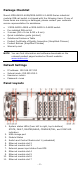
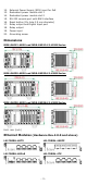
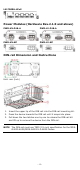
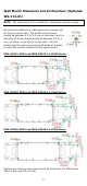
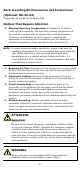
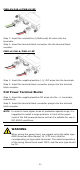
Table Of Contents
- MDS-G4000-4XGS/ MDS-G4000-L3-4XGS Series Quick Installation Guide
- Package Checklist
- Default Settings
- Panel Layouts
- Dimensions
- Ethernet Modules (Hardware Rev.2.0.0 and above)
- Power Modules (Hardware Rev.2.1.0 and above)
- DIN-rail Dimension and Instructions
- Wall Mount Dimension and Instructions (Optional: WK-112-01)
- Rack-mounting Kit Dimensions and Instructions (Optional: RK-3U-02)
- Matters That Require Attention
- Connecting the Power Inputs
- Power Terminal Blocks
- PoE Power Terminal Blocks
- Wiring the Relay Contact
- Digital Input/Output
- Installing and Removing the Ethernet Modules
- Installing and Removing the Power Modules
- Grounding the Moxa Industrial DIN-rail Switch
- RS-232 with RJ45 Interface Console Connection
- USB Storage Connection
- Resetting to Factory Default Settings
- LED Indicators
- Specifications
- Restricted Access Locations

- 3 -
12. External Power Supply (EPS) input for PoE
13. Redundant power module slot 1
14. Redundant power module slot 2
15. RS-232 console port with RJ45 interface
16. Reset button (Pin hole 0.9 mm diameter)
17. Relay output and Digital Input port
18. Relay output
19. Power input
20. Grounding screw
Dimensions
MDS-G4012-4XGS and MDS-G4012-L3-4XGS Series
MDS-G4020-4XGS and MDS-G4020-L3-4XGS Series
MDS-G4028-4XGS and MDS-G4028-L3-4XGS Series
Unit: mm (inch)
Ethernet Modules (Hardware Rev.2.0.0 and above)
LM-7000H-4GTX
LM-7000H-4GSFP
LM-7000H-4GPoE
LM-7000H-4TX