
Installation Guide
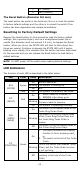
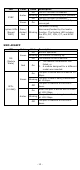
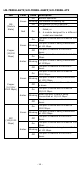
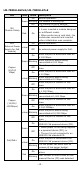
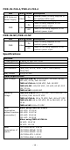
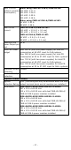
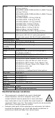
Table Of Contents
- MDS-G4000-4XGS/ MDS-G4000-L3-4XGS Series Quick Installation Guide
- Package Checklist
- Default Settings
- Panel Layouts
- Dimensions
- Ethernet Modules (Hardware Rev.2.0.0 and above)
- Power Modules (Hardware Rev.2.1.0 and above)
- DIN-rail Dimension and Instructions
- Wall Mount Dimension and Instructions (Optional: WK-112-01)
- Rack-mounting Kit Dimensions and Instructions (Optional: RK-3U-02)
- Matters That Require Attention
- Connecting the Power Inputs
- Power Terminal Blocks
- PoE Power Terminal Blocks
- Wiring the Relay Contact
- Digital Input/Output
- Installing and Removing the Ethernet Modules
- Installing and Removing the Power Modules
- Grounding the Moxa Industrial DIN-rail Switch
- RS-232 with RJ45 Interface Console Connection
- USB Storage Connection
- Resetting to Factory Default Settings
- LED Indicators
- Specifications
- Restricted Access Locations

- 19 -
ATTENTION
•
This device is an open-type equipment and should be
installed in a suitable enclosure.
•
Please use an optical transceiver (SFP) that complies with
IEC 60825-1, 21 CFR 1040 Section 1040.10 and 1040.11,
classified as Class 1 laser product.
•
If the equipment is used in a manner not specified by the
manufacturer, the protection provided by the equipment
may be impaired.
•
The installation and the safety of any system incorporating
the equipment is the responsibility of the assembler of the
system.
• For any repair or maintenance needs, please contact us.
NOTE
• This device is intended for use indoor and at altitudes up to
2000 meters.
•
Overvoltage category II.
• Pollution degree 2.