
Installation Guide
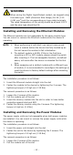
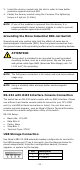
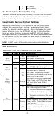
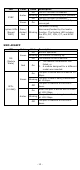
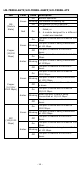
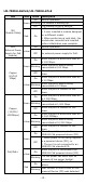
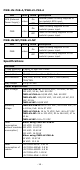
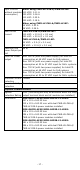
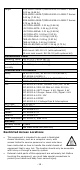
Table Of Contents
- MDS-G4000-4XGS/ MDS-G4000-L3-4XGS Series Quick Installation Guide
- Package Checklist
- Default Settings
- Panel Layouts
- Dimensions
- Ethernet Modules (Hardware Rev.2.0.0 and above)
- Power Modules (Hardware Rev.2.1.0 and above)
- DIN-rail Dimension and Instructions
- Wall Mount Dimension and Instructions (Optional: WK-112-01)
- Rack-mounting Kit Dimensions and Instructions (Optional: RK-3U-02)
- Matters That Require Attention
- Connecting the Power Inputs
- Power Terminal Blocks
- PoE Power Terminal Blocks
- Wiring the Relay Contact
- Digital Input/Output
- Installing and Removing the Ethernet Modules
- Installing and Removing the Power Modules
- Grounding the Moxa Industrial DIN-rail Switch
- RS-232 with RJ45 Interface Console Connection
- USB Storage Connection
- Resetting to Factory Default Settings
- LED Indicators
- Specifications
- Restricted Access Locations

- 13 -
LED
Color
State
Description
SYNC
Amber
On
The PTP function is enabled.
Blinking
The switch is receiving sync packets.
Off
The PTP function is disabled.
Green On
The PTP function has successfully
converged.
System LEDs
(Except
PWR)
Green/
Amber/
Red
Blinking
The switch is being
discovered/located by the locator
function. The System LED includes
the STA, FLT, M/H, C/T, and SYNC
LEDs.
SWC-4XGSFP
LED
Color
State
Description
MS
(Module
State)
Green
On
Normal operation.
Blinking
The module is booting up.
Off
The module is out of service.
Red On
1. The module initialization has
failed, or
2.
A module designed for a different
model was inserted.
SFP+
(10 GbE)
Green
On
The port is active and is linked at 10
Gbps.
Blinking
The port’s data is being transmitted
at 10 Gbps.
Off
The port is inactive or the link is
down.
Amber
On
When the port is active and is linked
at 1000 Mbps.
Blinking
The port’s data is being transmitted
at 1000 Mbps.
Off
The port is inactive or the link is
down.