
Installation Guide
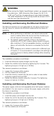
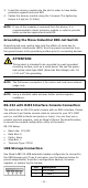
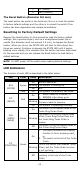
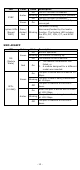
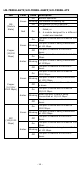
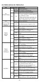
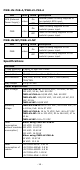
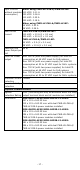
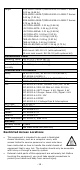
Table Of Contents
- MDS-G4000-4XGS/ MDS-G4000-L3-4XGS Series Quick Installation Guide
- Package Checklist
- Default Settings
- Panel Layouts
- Dimensions
- Ethernet Modules (Hardware Rev.2.0.0 and above)
- Power Modules (Hardware Rev.2.1.0 and above)
- DIN-rail Dimension and Instructions
- Wall Mount Dimension and Instructions (Optional: WK-112-01)
- Rack-mounting Kit Dimensions and Instructions (Optional: RK-3U-02)
- Matters That Require Attention
- Connecting the Power Inputs
- Power Terminal Blocks
- PoE Power Terminal Blocks
- Wiring the Relay Contact
- Digital Input/Output
- Installing and Removing the Ethernet Modules
- Installing and Removing the Power Modules
- Grounding the Moxa Industrial DIN-rail Switch
- RS-232 with RJ45 Interface Console Connection
- USB Storage Connection
- Resetting to Factory Default Settings
- LED Indicators
- Specifications
- Restricted Access Locations

- 12 -
3
D+ (Data+)
4
GND (Ground)
The Reset Button (diameter 0.9 mm)
The reset button can perform two functions. One is to reset the switch
to factory default settings and the other is to reboot the switch if the
button has been depressed and release immediately.
Resetting to Factory Default Settings
Depress the Reset button for five seconds to load the factory default
settings. Use a pointed object, such as a straightened paper clip or
needle (the diameter must not exceed 0.9 mm), to depress the Reset
button. When you do so, the STATE LED will start to blink about four
times per second. Continue to depress the STATE LED until it begins
blinking more rapidly; this indicates that the button has been depressed
for five seconds and you can release the Reset button to load factory
default settings.
NOTE
Do NOT power off the switch when loading default settings.
LED Indicators
The function of each LED is described in the table below.
LED
Color
State
Description
System LEDs
STA
(STATE)
Green
On
Normal operation.
Blinking
The system is booting up.
Off
N/A
Red
On
The system initialization has failed.
FLT
(FAULT)
Red
On
1. Switch failed to initialize, or
2. EEPROM information error.
Blinking
The switch boots up and the
firmware loads to memory.
Off
The system is operating normally.
M/H
(MSTR/
HEAD)
Green
On
The switch is the Master/Head of the
Turbo Ring/Turbo Chain.
Blinking
The switch is the Ring Master/Head
of the Turbo Ring/Turbo Chain and
the Turbo Ring/Turbo Chain is
broken.
Off
The switch is not the Master/Head of
this Turbo Ring/Turbo Chain.
C/T
(CPLR/TAIL)
Green
On
1. The switch enables the coupling
function to form a backup path,
or
2. The switch is the tail of the
Turbo
Chain.
Blinking
This is the switch that enables Turbo
Chain, but the Turbo Chain function
is not working.
Off
When the switch disables the
coupling or tail role of the Turbo
Chain.