
Installation Guide
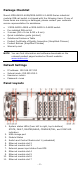
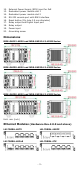
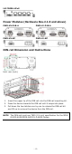
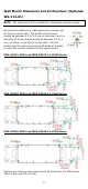
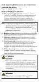
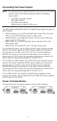
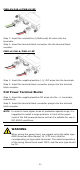
Table Of Contents
- MDS-G4000-4XGS/ MDS-G4000-L3-4XGS Series Quick Installation Guide
- Package Checklist
- Default Settings
- Panel Layouts
- Dimensions
- Ethernet Modules (Hardware Rev.2.0.0 and above)
- Power Modules (Hardware Rev.2.1.0 and above)
- DIN-rail Dimension and Instructions
- Wall Mount Dimension and Instructions (Optional: WK-112-01)
- Rack-mounting Kit Dimensions and Instructions (Optional: RK-3U-02)
- Matters That Require Attention
- Connecting the Power Inputs
- Power Terminal Blocks
- PoE Power Terminal Blocks
- Wiring the Relay Contact
- Digital Input/Output
- Installing and Removing the Ethernet Modules
- Installing and Removing the Power Modules
- Grounding the Moxa Industrial DIN-rail Switch
- RS-232 with RJ45 Interface Console Connection
- USB Storage Connection
- Resetting to Factory Default Settings
- LED Indicators
- Specifications
- Restricted Access Locations

- 10 -
WARNING
When wiring the Digital Input/Output contact, we suggest using
the cable
type - AWG (American Wire Gauge) 16-28 (1.31-
0.081 mm
2
) and the corresponding pin type cable terminals.
The rated temperature of the wiring should be at least 105°C
and the wire type should be CU.
Installing and Removing the Ethernet Modules
The Ethernet modules are hot-swappable for the same module type.
You can mount or remove the Ethernet module while the device is
operating.
NOTE
1.
When performing a cold start, you cannot remove and
insert a module before the device has fully booted up as
this will cause the module to fail initialization.
2.
The default module is 4XGS. If this is the first time
mounting a 4TX or SFP module, please reboot the switch
after inserting it. The hot-swappable function, as defined
above, will work after the device is rebooted for the first
time.
3.
When swapping out a slotted module with a different type
of module, it is recommended to reconfigure the settings
or
reset the device to factory default settings after rebooting
the switch.
The installation procedure is as follows:
1. Insert the Ethernet module straight into the slot
2. Fasten the module to the device by tightening the 2 screws. The
tightening torque is 3.5 kgf-cm (0.35 Nm)
The removal procedure is as follows:
1. Loosen the 2 screws of the module
2. Pull the module out of the slot
3. Insert the dummy module into the slot in order to have better
protection against dust and EMI
4. Fasten the dummy module using the 2 screws. The tightening
torque is 4 kgf-cm (0.4 Nm)
Installing and Removing the Power Modules
The power supply units are hot-swappable when both power modules
are installed. You can mount or remove the power supply units while
the device is operating.
The installation procedure is as follows:
1. Insert the power unit straight into the slot
2. Fasten the unit to the device by tightening the 2 screws. The
tightening torque is 3.5 kgf-cm (0.35 Nm)
The removal procedure is as follows:
1. Loosen the 2 screws of the module
2. Pull the module out of the slot