
User Manual

- 4 -
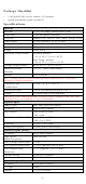
Thermocouple Input
Sensor Type
J, K, T, E, R, S, B, N
Millivolt Type
±78.126 mV, ±39.062 mV, ±19.532 mV
Fault and Overvoltage
protection
±35 VDC (power off); +30 VDC, -25 VDC
(power on)
Sampling Rate
12 samples/sec (all channels)
Resolution
16 bits
Accuracy
±0.1% FSR @ 25°C
±0.3% FSR @ -40 and 75°C
Input Impedance
10M ohms
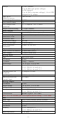
Installation
Jumper Settings
Models with DIO, AI, or external power channels require configuring the
jumpers inside the enclosure. Remove the screw located on the back
panel and open the cover to configure the jumpers.
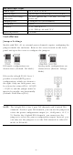
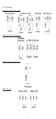
DIO mode configurations are
shown above (Default: DO Mode).
Analog mode configurations are
shown above (Default: Voltage
Mode).
DOs on the ioLogik E1213 have 3
possible external (EXT) power
configurations, which are shown to
the right. Only one field power can
be selected at a time (JP10 / 12V JP5
/ 9V JP11)
and
the jumper must be
inserted ver
tically, not horizontally
(Default: Field Power JP10).
NOTE
The ioLogik E1213 has 4 pure DO channels and 4 hybrid DIO
channels. For the 4 pure DO channels, you can use the jumpers to
select the power configuration output (i.e., field power, 12 V, 9
V). But for the 4 hybrid DIO channels, you cannot use the
jumpers to select th
e power configuration output. Instead, you
can only use the jumpers to set the DIO channels to either DI
mode or DO mode.