ioThinx 4510 Series Quick Installation Guide Edition 1.0, August 2018 Technical Support Contact Information www.moxa.
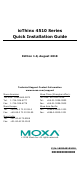
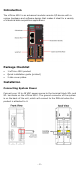
Introduction The ioThinx 4510 is an advanced modular remote I/O device with a unique hardware and software design that makes it ideal for a variety of industrial data acquisition applications. Package Checklist • • • 1 ioThinx 4510 product Quick installation guide (printed) 2 side cover plates Installation Connecting System Power Connect your 12 to 48 VDC power source to the terminal block SP+ and SP- terminals on the ioThinx 4510.
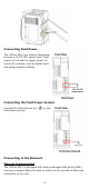
Connecting Field Power The ioThinx 4510 can receive field power through a 12/24 VDC power input. Field power can be used to supply power for some I/O modules, such as digital input and analog output modules. Connecting the Field Power Ground Connect the Field Ground pin ( field power ground. ) to the Connecting to the Network Ethernet Communication The ioThinx 4510 is equipped with dual unmanaged LAN ports (RJ45).
Serial Communication The ioThinx 4510 is equipped with a 3-in-1 serial interface, which supports 1 RS-232 port, or 1 RS-422 port, or 2 RS-485 ports. Follow the pin assignment table below to set up serial connection to the unit. PIN 1 2 3 4 5 RS-232 (P1) TXD RXD RTS CTS GND RS-422 (P1) TXD+ TXDRXD+ RXDGND RS-485 (P1/P2) DATA 1+ DATA 1DATA 2+ DATA 2GND 45M Module Wiring For detailed 45M module wiring, refer to the ioThinx 4510 User Manual on the official website.
Installing a 45M Module on a DIN-Rail Step 1: Align the 45M module side by side with the head/CPU module, making sure that the upper and lower rails are hooked together. Step 2: Align the 45M module side by side with the head/CPU module and then push the 45M module until it touches the DIN-rail. Next, apply more force until the module clips to the DIN-rail. NOTE After the module is firmly attached to the DIN-rail, the module connections to the internal bus will be established.
Step 2: Push the top of the release tab to latch it, and then pull the module out. NOTE Electrical connections for internal bus will be disconnected when removing the 45M module. WARNING Be sure the power is off before removing modules to avoid unexpected damage. Installing the Covers on the First and Last Module Attach the covers to the first and last module to cover the modules’ contacts. NOTICE Be sure to attach the covers to provide electrostatic discharge protection.
LED Indicators Name Indication LED Qty Description SP System 1 On: Power on Power Off: Power off FP Field Power 1 On: Power on Off: Power off RDY System 1 Green: System ready (Kernel) Green Slow Blinking: Booting up Ready Red: System error Red Slow Blinking: Loading Factory Default Recovery/Upgrading firmware/Backup mode Red Fast Blinking: Safe mode Off: Power off LAN Ethernet 1 for Green: 100Mb connection Connection each port Amber: 10Mb connection Blinking: Data transmitting Off: Disconnected Px Serial 1
How to Download the Software Related software packages can be downloaded from the Moxa website. Step 1: Go to the following address to open the Support & Downloads search tool: http://www.moxa.com/support/support_home.aspx?isSearchShow=1 Step 2: Type the model name in the search box or select a product from the drop-down box and then click Search. The ioLogik E1210 is used for the examples below. Step 3: Go to the Software page to download the latest software for the product.