
User Manual

ioThinx 4510 Series Software Tools
4-20
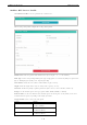
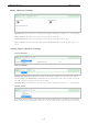
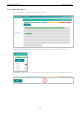
DI Mode
Filter: Software filtering is used to avoid switch bounces (unit: 500μs, 0 to 65535).
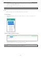
Counter Mode
Filter: Software filtering is used to avoid switch bounces (unit: 500μs, 0 to 65535).
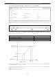
Power on Value: The initial counter value upon powering up (0 to 4294927695).
Power on Status: The counter status upon powering up (option: ON or OFF).
Power off Storage: Save counter value to memory during powering off. The saved value will be the initial
value upon next powering up (option: ON or OFF).
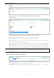
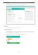
Trigger: The channel accepts limit or proximity switches and counts events according to the ON/OFF status.
When Rising edge is selected, the counter value increases when the attached switch is pushed. When Falling
edge is selected, the counter value increases when the switch is released. When Both is selected, the counter
value increases when the attached switch is pushed or released (option: Rising edge, Falling edge, or Both).
NOTE
Not all DI channels support counter mode. Refer to
the ioThinx 4500 Series (45MR) Modules
datasheet for
detailed
specifications.
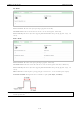
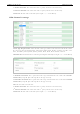
Digital Output Channel Settings
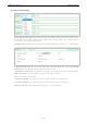
Channel Mode Drop-Down List: It lists all of the channel modes, which can be operated by this channel.
Select DO or Pulse mode for each channel (option: DO or Pulse).
Channel Name: The channel name is used for representing this channel (max. length = 16, “.” is not allowed).