
User Manual

ioThinx 4510 Series Hardware Installation
3-2
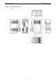
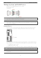
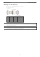
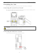
Wiring System and Field Power
Wire range: 12 to 26 AWG (Ferrule diameter: 2.0 to 0.4 mm)
Wire strip length: 10 mm
Unit: mm (in.)
NOTE
P
owering the unit requires connecting both the system and field power to the
power supply. If only one of the
power
sources is connected, the device may not work properly.
NOTE
W
e recommended using different power supplies to ensure that the system power and field power
are isolated
from each other
. If using the same power supply for system power and field power, 3 KV or above isolation
between them is recommended.
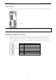
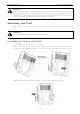
System Power
This device requires a 12 to 48 VDC system power input. The system power powers this device and the
expansion modules via an internal bus, which is galvanically connected to the system power supply.
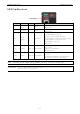
The amount of system current required to support an expansion module is 1 A. If more modules and more
power consumption is needed, an additional power module (45MR-7210) is required. Below is an example:
• 10 x 45MR-1600 (59.4 mA) = 594 mA
• 5 x 45MR-3810 (187 mA) = 935 mA
The total system current is 1.594 A, which is greater than 1 A. Therefore, an additional 45MR-7210 is needed.
NOTE
Install the 45MR
-7210 to the left hand side of
the module where the power consumption would be exceeded.
NOTE
To avoid damaging your devices, r
eset all power supplies connected to this device and 45MR-7210 modules
at
the same time
.