ioThinx 4510 Series User’s Manual Edition 1.0, November 2018 www.moxa.com/product © 2018 Moxa Inc. All rights reserved.
ioThinx 4510 Series User’s Manual The software described in this manual is furnished under a license agreement and may be used only in accordance with the terms of that agreement. Copyright Notice © 2018 Moxa Inc. All rights reserved. Trademarks The MOXA logo is a registered trademark of Moxa Inc. All other trademarks or registered marks in this manual belong to their respective manufacturers.
Safety Symbols DANGER Indicates a high-risk, imminently hazardous situation which, if not avoided, will result in death or serious injury. WARNING Indicates a moderate risk, which, if not avoided can cause a potentially hazardous situation. CAUTION Indicates a low-risk, potentially hazardous situation which, if not avoided, may result in minor or moderate injury. NOTE Indicates a potential malfunction which, if not avoided, will not result in damage to property.
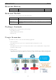
Table of Contents 1. Preface .............................................................................................................................................. 1-1 Revision History ................................................................................................................................. 1-2 Relevant Models ................................................................................................................................. 1-2 Package Contents .................
Backing up Configuration Files .................................................................................................... 5-17 Updating the Firmware ............................................................................................................... 5-17 Restarting the Unit .................................................................................................................... 5-18 Loading Factory Default Settings .............................................................
1 1. In this chapter, we explain the scope of and how to use this document.
ioThinx 4510 Series Preface Revision History Version Change Date V1.0 First Release 2018-11-12 Relevant Models This document is only applicable to the models listed below. Model Name Description ioThinx 4510 Advanced I/O, Ethernet network adapter, 3-in-1 serial port(s), -20 to 60°C operating temperature ioThinx 4510-T Advanced I/O, Ethernet network adapter, 3-in-1 serial port(s), -40 to 75°C operating temperature Package Contents The following items are included in the product package.
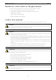
ioThinx 4510 Series Preface Hardware and Software Requirements You will need the following hardware and software to use the ioThinx 4510 Series.
ioThinx 4510 Series Preface WARNING Check the voltage or current of the sensors or loads. Make sure the voltage and/or current indicated on the sensors or loads corresponds to the specifications of your 45M module before you connect the device. WARNING Connect your device to an earthed ground. CAUTION Do not use the device if the device is already damaged. Replace defective or damaged devices to ensure that your devices function properly. CAUTION Do not attempt to repair the device yourself.
2 2. Product Overview In this chapter, we give an overview of each of the 45MR modules.
ioThinx 4510 Series Product Overview Technical Data Common Specifications Input/Output Interface Expansion Modules: Up to 32 Note: Compatible with 45MR Series only Ethernet Interface 10/100BaseT(X) Ports (RJ45 connector): 2 Ethernet Software Features Industrial Protocols: Modbus TCP Server (Slave) RESTful API SNMPv1/v2c/v3 Serial Interface Serial Standards: 1 x RS-232/422 or 2 x RS-485 (2-wire) Connector: Removable Terminal block Wiring: 16 to 28 AWG Serial Software Features Industrial Protocols: Modb
ioThinx 4510 Series Product Overview Appearance Front View 2-3
ioThinx 4510 Series Product Overview Physical Dimensions Unit: mm (in) 2-4
ioThinx 4510 Series Product Overview LED Indicators Labeling SP FP Indication System Power Field Power LED Qty LED Color 1 Green 1 Green LED Action On: power on Off: power off On: power on Off: power off Green: system ready Green slow blinking: booting up RDY System (Kernel) Red: system error or module mismatch 1 Green/Red Red slow blinking: loading factory default settings, upgrading firmware, or system recovery Red fast blinking: safe mode Off: power off Green: 100mb L1/L2 Ethernet 1 fo
3 3. Hardware Installation In this chapter, we describe how to install the 45MR modules.
ioThinx 4510 Series Hardware Installation Wiring System and Field Power Wire range: 12 to 26 AWG (Ferrule diameter: 2.0 to 0.4 mm) Wire strip length: 10 mm Unit: mm (in.) NOTE Powering the unit requires connecting both the system and field power to the power supply. If only one of the power sources is connected, the device may not work properly. NOTE We recommended using different power supplies to ensure that the system power and field power are isolated from each other.
ioThinx 4510 Series Hardware Installation Field Power This device provides 12/24 VDC field power input, which is a passive power supply without protection and the maximum current output is 2 A. NOTE The 12/24 VDC field power supply can be connected directly to 45MR modules. If more connection points are needed, purchase 45MR-7820 (8 x FP+ and 8 x FP-) modules.
ioThinx 4510 Series Hardware Installation Wiring Serial Port(s) Wire range: 16 to 28 AWG (Ferrule diameter: 1.2 to 0.3 mm) Wire strip length: 9.0 mm Unit: mm (in.) NOTE Pin RS-232 RS-422 RS-485 (P1/P2) 1 TXD TXD+ DATA1+ 2 RXD TXD- DATA1- 3 RTS RXD+ DATA2+ 4 CTS RXD- DATA2- 5 GND GND GND Connect the signal common pin (e.g. GND pin on the serial port pin assignment) between each of the serial device units.
ioThinx 4510 Series Hardware Installation Grounding the Unit This device has two ground pins. One pin is for system power and the other pin is for field power. Connecting the System Power Ground The system power ground connector is at the back of the unit. Once the device has been installed on a DIN rail, the system power ground connector will connect to the DIN rail. CAUTION For surge protection, connect the DIN rail to earth ground.
ioThinx 4510 Series Hardware Installation CAUTION Be sure to note the maximum possible current for each power wire and common wire. Observe all electrical codes dictating the maximum current allowable for each wire size. If currents exceed the maximum rating, the wires will overheat, which could cause serious damage to your equipment. For safety reasons, we recommend using 2 mm diameter wire to connect to the power supply (e.g., 12 AWG).
ioThinx 4510 Series INFORMATION Hardware Installation When the I/O module is inserted into the correct position, the connection between the internal bus and the previous module is established. Removing the Unit from a DIN Rail Take the following steps to remove the unit from a DIN rail. Step 1: Use your finger to pull the release tab on the lower part of the module. Step 2: Press the release tab (item 1 in the figure) and then remove the CPU module from the DIN rail (item 2 in the figure).
ioThinx 4510 Series Hardware Installation Installing Covers on the Device and the Right-Most I/O Module Insert the covers on the left side of the device and on the right side of the I/O module that is installed furthest to the right. Make sure the covers cover the internal bus of the module. NOTE The covers provide protection against electrostatic discharge. Removing a Cover from the Right-Most Module Before adding a new module to the right-most module, remove the cover first.
ioThinx 4510 Series Hardware Installation Horizontal Installation Before installing the device, ensure there is enough space around the device so that it can dissipate heat. In order to ensure the device works properly, we suggest reserving the space shown in the figure below. CAUTION DO NOT install the device vertically, as the fan-less heat dissipation design will not perform as intended.
4 4. Software Tools In this chapter, we introduce which software tools can be used with this device.
ioThinx 4510 Series Software Tools Preparing Software Tools Connecting Web Console The Web Console is already embedded in this device. Use the web console to check the device status, configure settings, or update the firmware of the device. Follow the steps below to connect to the web console. 1. Connect the device to your PC through an Ethernet cable. 2. Power on the unit. 3. Open a web browser (Chrome is recommended) on your PC, and type the default IP address shown on the model label of the unit.
ioThinx 4510 Series Software Tools Web Console The Web Console is the main software tool to configure, monitor, and operate a device. If mass deploying to multiple devices is required, use IOxpress utility instead. The Web Console is divided into three regions: 1. Title Panel: It provides Login, Save & Restart, and Logout functions. 2. Menu panel: It provides access to configure the functions or services. 3. Web page panel: The web page associated with the function selected in the Menu panel.
ioThinx 4510 Series Software Tools Dashboard The dashboard provides information about the system, modules, I/Os, and the connection status. It also allows you to exit the safe mode status or to change the I/O status. System Information The one page system information provides detailed information for this device. For information regarding modules and I/Os, click Module & I/O to get the detailed information. For the status of external connections, click Connection to get the detailed information.
ioThinx 4510 Series Software Tools Module & I/O The Module & I/O provides information about modules and I/Os status. It also allows you to change the I/O status. Module Drop-Down List: It lists all of the I/O modules of this device. Select the specific module for its module and I/O information. Locate: Identify the physical location of the module and the module’s status LED will blink green. DI Channel (DI Mode): It shows the status of this channel. No operation is allowed.
ioThinx 4510 Series Software Tools DO Channel (Pulse Mode): It shows the status of this channel. Click START or STOP to change the pulse output status. Relay Channel: It shows the status of this channel. Click ON or OFF to change the relay status. AI Channel: It shows the status of this channel. Click RESET to reset the minimum and maximum values. RTD Channel: It shows the status of this channel. Click RESET to reset the minimum and maximum values. TC Channel: It shows the status of this channel.
ioThinx 4510 Series Software Tools System This section introduces the functions of the device’s system. Device Settings Device Name: Set the name of this device (max length = 16, '.' is not allowed). Language: Select the language of the web console. Time Settings System Date & Time: Select the date for the device. Click Set Time to set the time of the device. Enable NTP Server: Click the checkbox to enable date and time synchronization with the NTP sever.
ioThinx 4510 Series Software Tools Watchdog Safe Mode on Service: Select the service that you want to link the watchdog to in order to keep monitoring the connection status (option: Modbus TCP Slave). Communication Watchdog for Safe Mode: The timeout value when the master of Safe Mode on Service is disconnected (unit: sec(s), 0 to 65535, 0 is disable). Auto Clear Safe Mode: Click the checkbox to enable or disable automatically clearing the safe mode status.
ioThinx 4510 Series Software Tools Configuration Select File: Click Browse to select a configuration file to update the device. Update network settings (IP, Gateway, etc.): Click the checkbox if the network settings need to be updated. Update to Device: Click Update to update the firmware to the device. Get from Device: Get the configuration file of the device. Load to Default: Load the factory default settings of the current firmware version.
ioThinx 4510 Series Software Tools NOTE Do not disconnect the power or network cable during the update process. NOTE This device supports firmware automatic recovery function. If the firmware in the device is corrupted, the system will load the backup firmware automatically to overwrite the corrupted one. When the system is in recovery mode, the RDY LED will slowly blink red. DO NOT DISCONNECT the power cable when the recovery process is underway.
ioThinx 4510 Series Software Tools User Settings Enable/Disable user type, or configure the username and password for Administrator, Operator, and Users. Type: Select a user type to change the username and password. Enable: Enable or disable the type you select. New Username: It allows you to change the username of the selected user type (Must be 1 to 30 characters in length. Letters, numbers, and symbols are allowed, but not spaces).
ioThinx 4510 Series Software Tools Account Settings Idle Timeout: The timeout value when the user account is idle (unit: min(s), 0 to 1440 mins, default: 5 mins) Note: 0 for disabled. Retry Failure Threshold: The maximum number of retries for the user account to log in (unit: time(s), 1 to 10 times, default: 5 times). Lockout Time: The timeout value for when the user account will be locked due to reaching the retry failure threshold (unit: min(s), 1 to 60 mins, default: 5 mins).
ioThinx 4510 Series Software Tools Network This section introduces the Network settings function. LAN Settings IP Configuration: Configure the following settings if Static IP is selected. If DHCP is selected, the following settings are not allowed (option: Static IP or DHCP). IP Address: Set the IP address of the device (0 to 255). Netmask: Define the logical subdivision of an IP network and specify the network's available hosts (0 to 255).
ioThinx 4510 Series Software Tools Edit: Click this button to enter edit mode. Save Settings: This button only appears in edit mode. Click this button to finish module settings and exit edit mode. Cancel: This button only appears in edit mode. Click this button to cancel module settings and exit edit mode. Auto Matching Load Default Reload : Click this button to automatically match all configured modules with all detected modules.
ioThinx 4510 Series NOTE Software Tools The detected module should match the configured module. Otherwise, the Web Console will not allow you to configure other settings. NOTE The detected module should match the configured module. Otherwise, the Web Console will not allow you to click Finish. INFORMATION Use Auto Matching to quickly match the configured module with the detected module.
ioThinx 4510 Series Software Tools Serial Port This section introduces the serial port settings function. Port 1/Port 2 Click the tab to configure the settings of Port 1 or Port 2. NOTE The Port 2 tab is only available when the Mode of the Port 1 is RS-485 2-Wire. Mode: The standard of the serial device connected to this port (option: RS-232, RS-422, or RS-485 2-Wire). Baudrate: The data transmission rate (option: 300, 1200, 2400, 4800, 9600, 19200, 38400, 57600, or 115200 bps).
ioThinx 4510 Series Software Tools Modbus RTU Device Device Drop-Down List: It shows the device name of the Modbus RTU devices. Select one of the devices to configure its settings. The green icon shows that data collection from the device is enabled. Enable Device: Click the checkbox to enable data collection from the device. The icon beside the Modbus device in the Device Drop-Down List will change from red to green after being enabled. Device Name: Name of the Modbus device (max. length = 16; “.
ioThinx 4510 Series Software Tools Modbus RTU Device Profile Click Add New Profile to create a profile of the selected device. After creating a new profile, configure the settings of the profile. Profile Name: Name the profile of the Modbus device (max. length = 16; “.” is not allowed).
ioThinx 4510 Series Software Tools Exception Code Setting - WORD IR Index: Set the internal register for exception code. It only allows you to select one of the available internal registers. Delete this Profile: Click this button to delete this profile. NOTE The maximum number of Modbus RTU device profiles that can be created is 8. I/O This section introduces the I/O and IR (Internal Register) settings functions. I/O Settings Module Drop-Down List: It lists all the I/O modules of this device.
ioThinx 4510 Series Software Tools DI Mode Filter: Software filtering is used to avoid switch bounces (unit: 500μs, 0 to 65535). Counter Mode Filter: Software filtering is used to avoid switch bounces (unit: 500μs, 0 to 65535). Power on Value: The initial counter value upon powering up (0 to 4294927695). Power on Status: The counter status upon powering up (option: ON or OFF). Power off Storage: Save counter value to memory during powering off.
ioThinx 4510 Series Software Tools DO Mode Power on Status: The DO status upon powering up (option: ON or OFF). Safe Mode Status: The DO status when the device is in safe mode (option: ON or OFF). Power on Delay: The time delay before triggering Power on Status after powering up (unit: sec(s), 0 to 65535). Pulse Mode Power on Status: The Pulse status upon powering up (option: ON or OFF). Safe Mode Status: The Pulse status when the device is in safe mode (option: ON, OFF, or Hold Last).
ioThinx 4510 Series Software Tools Relay Channel Settings Channel Name: The channel name is used for representing this channel (max. length = 16, “.” is not allowed). Power on Status: The Relay status upon powering up (option: ON or OFF). Safe Mode Status: The Relay status when the device is in safe mode (option: ON or OFF). Power on Delay: The time delay before triggering Power on Status after powering up (unit: sec(s), 0 to 65535).
ioThinx 4510 Series Software Tools 0-20 mA/4-20 mA burnout/4-20 mA/0-10 V/±10 V Mode Burnout Value (only for 4-20 mA burnout mode): The 4–20 mA burnout mode is shown in the diagram below. The Burnout Value (default = 2 mA) is definable (unit: mA, 0.000 to 4.000). When input values are in the burnout range, raw data will register as 0000h to indicate that the analog input has burned out. The definition of raw data can be found in the table below. Range Modbus Data 0.
ioThinx 4510 Series Software Tools 1st Point Scaled Value: The scaled value of the 1st point (-4294967295 to 4294967295). 2nd Point Scaled Value: The scaled value of the 2nd point (-4294967295 to 4294967295). Scaled Unit: The unit of the scaled value (max. length = 8, “.” is not allowed). RTD Channel Settings Sensor Type Drop-Down List: It lists all of the sensor types, which can be connected to this channel.
ioThinx 4510 Series Software Tools TC Channel Settings Sensor Type Drop-Down List: It lists all of the sensor types, which can be connected to this channel. Select the sensor type for each channel (option: J Type, K Type , T Type , E Type , R Type , S Type , B Type , N Type , ±19.532 mV, ±39.062 mV, or ±78.126 mV). Channel Name: The channel name is used for representing this channel (max. length = 16, “.” is not allowed).
ioThinx 4510 Series Software Tools Internal Register This section introduces functions of Internal Register settings. IR Type Drop-Down List: It lists all of the IR types. Select the IR type to modify or view its settings. IR Quantity: Apply a number to adjust the quantity of the selected IR type. The total available IR quantity is 256.
ioThinx 4510 Series Software Tools IR Information: The IR status window will pop-up after you click one of the IR blocks. The name is used for representing this internal register (max. length = 16, “.” is not allowed). Protocol This section introduces the protocol settings functions. Modbus TCP Slave The Modbus TCP Slave section shows the definition of the device’s Modbus registers. It allows you to define your own data point type or address of the Modbus registers.
ioThinx 4510 Series Software Tools Reload Configuration: Click this button to reload the configuration settings of all Modbus registers. Filter: Type characters into the textbox to filter the items in the Modbus Table. Point Type Category: Click 01: Coil Status (R/W), 02: Input Status (R), 03: Holding Register (R/W), or 04: Input Register (R) tab to see the registers under the specific point type.
ioThinx 4510 Series Software Tools Start Address Textbox: Change the value of the Start Address in the textbox (0 to 65535 or leave it blank). When there is no value in the textbox, it will be displayed in light yellow. When it conflicts with another register, it will be displayed in red. Revise the value to prevent address conflict. You can use the Sort function to see where there is a conflict of addresses. Sort: The default-sorted column is the Slot from the lowest to highest slot number.
ioThinx 4510 Series INFORMATION Software Tools Enable/disable this service through Security Service Settings. SNMPv1, SNMPv2c Settings Read Community: Type the community string matching for read authentication (max length = 30, default = "public"). Write Community: Type the community string matching for write authentication (max length = 30, default = "private"). SNMPv3 Settings – Read Only Username: Type the username for SNMP v3 settings (min.
ioThinx 4510 Series Software Tools SNMPv3 Settings – Read/Write Username: Type the username for the SNMP v3 settings (min. length = 1; max length = 30; A to Z, a to z, 0 to 9, symbols, spaces are not allowed, default = "v3rw"). Authentication Protocol: Select Disable, MD5, or SHA for the authentication protocol settings (default: MD5). Authentication Password: Type the password for the authentication password settings (min.
5 5.
ioThinx 4510 Series Quick Start Guide Configuring the Unit This section explains how to configure this device through the Web Console from the beginning. If you require additional information, please refer to Preparing Software Tools before reading this section. Login to the Unit Follow the steps to log in to the unit. Step 1: Open your web browser and type the default IP address of the device, 192.168.127.254.
ioThinx 4510 Series Quick Start Guide If you see the module settings page as opposed to the dashboard, click Edit to enter the edit mode and start editing the module settings. In edit mode, if any detected module and configured module do not match, the configured module will be highlighted as shown below. Click Auto Matching to match the conflicted modules. If not, you can use the “Auto Match” function or swap the module to change the module sequence.
ioThinx 4510 Series Quick Start Guide Changing Device Name Set the name of this device through System Device Settings. We recommend choosing a unique name for the device in order to easily differentiate it from other devices. Changing Username & Password In order to have higher levels of security, we recommend changing the username and password after your first log in. Click Security User Settings as shown in the screenshot below.
ioThinx 4510 Series Quick Start Guide Configuring Service Settings Click Security on the menu panel to enter the security settings page as shown below. For service settings, the user can enable or disable the service in order to control access. Configuring Account Settings For account settings, the user can modify the parameters and define the login failure message and system usage notifications.
ioThinx 4510 Series Quick Start Guide Configuring Network Settings Click Network on the menu panel to enter the network settings page as shown below. The ioThinx 4510 Series supports Ethernet daisy-chain topology with one MAC address. For this LAN port, it supports static IP and DHCP mode. The user can configure it via the LAN settings. Configuring Serial Port & IR Settings Click Serial Port on the menu panel to enter the serial port settings page.
ioThinx 4510 Series Quick Start Guide Click Internal Register on the menu panel to enter the internal register settings page. For more detailed information, please refer to the Internal Register chapter. Configuring I/O Settings Click I/O on the menu panel to enter the I/O settings page. For more detailed information, please refer to the I/O Settings chapter.
ioThinx 4510 Series Quick Start Guide Configuring Modbus Address Settings Click Modbus on the menu panel to enter the Modbus TCP Slave setting page. On this page, users can see all of the Modbus TCP addresses categorized by coil status, input status, holding register, and input register. To change Modbus addresses, users can click Reload default Modbus address, Reload current device address, or manually modify the addresses.
ioThinx 4510 Series Quick Start Guide Configuring SNMP Settings Click SNMP on the menu panel to enter the SNMP settings page as shown below. The ioThinx 4510 Series supports SNMP V1, V2c, and V3 and after configuring it, please download the mib file from Moxa’s website. For detailed information on the structure of the mib file, please refer to the SNMP chapter.
ioThinx 4510 Series Quick Start Guide Mass-deploying the Settings The mass-deploying function can be performed by IOxpress utility. IOxpress is a Windows utility and the system requirements are listed below: OS NOTE Microsoft Windows 2000, XP or later CPU Intel Pentium 4 CPU or higher RAM Min. 512 MB, 1024 MB is recommended Network 10/100 Ethernet The ioThinx 4510 Series is only compatible with IOxpress v2.3 or later.
ioThinx 4510 Series Quick Start Guide Step 3: Open IOxpress, go to the Device Library and click Device Search in the menu.
ioThinx 4510 Series Quick Start Guide Step 4: In the Search for Devices window, choose the product series you would like to search for in the By Product Series dropdown menu, and then click Submit. IOxpress will start to search the devices and list them in the table. NOTE If the devices cannot be found, check the network setting of the devices.
ioThinx 4510 Series Quick Start Guide Updating Configuration to Multiple Units IOxpress supports updating configuration of multiple units. Follow the steps to complete this task. Step 1: Export the configuration file of a device through the Web Console. Refer to Backing up Configuration Files for more details. Step 2: Select Update Configuration to Device in the dropdown menu. Step 3: Click the File column of the selected device in the table and then choose the configuration file from Step 1.
ioThinx 4510 Series Quick Start Guide Setting Date and Time to Multiple Units The IOxpress supports setting the date and time of multiple units. Follow these steps to complete this task. Step 1: Select Set Device Date & Time in the dropdown button Step 2: Select either Sync with PC or Manual Setting. For Manual Setting, type the Local Date and Time, which will be set on the device(s). Step 3: Select the device(s), type the Username and Password, and then click Submit.
ioThinx 4510 Series Quick Start Guide Monitoring & Operating the Unit To monitor and operate the device, go to the Dashboard of the Web Console. INFORMATION The ioThinx 4510 Series supports three different user profiles (Administrator, Operator, and User). Refer to User Settings for the permission information of each profile. Monitoring Module & I/O Status Under the Dashboard of the Web Console, click Module & I/O to go to the module and I/O status web page.
ioThinx 4510 Series Quick Start Guide Monitoring Connection Status Under the Dashboard of the Web Console, click the Connection button to go to the connection status web page. The connection status page lists the connection information from other hosts. NOTE Some browsers may create more than one Web Https connection at the beginning. Once the connection is established, the browsers will only keep one and drop the others.
ioThinx 4510 Series Quick Start Guide Maintaining the Unit This section introduces the maintenance functions of the ioThinx 4510 Series. Backing up Configuration Files This device can only be configured through the web console. After configuration, the configuration file can be retrieved from the device to perform backup and mass deployment. Follow the steps to retrieve the configuration file from the device.
ioThinx 4510 Series NOTE Quick Start Guide Performing a firmware update will delete the configurations in the device. Backup the configurations before performing the firmware update. Restarting the Unit This device will restart automatically after the firmware and configurations have been updated. The user can also restart the device manually. Step 1: Click Save & Restart on the right upper corner of the page. Step 2: The device will confirm that you want to perform a restart.
ioThinx 4510 Series Quick Start Guide Loading Factory Default Settings There are three ways to restore the device to factory default settings. 1. Follow the steps to load the factory default settings from the web console. Step 1: Go to the configuration page via Menu System Configuration Step 2: Click Reset located under Load to Default and then the device will return to default settings. NOTE Loading the factory default settings will delete the configurations from this device.
ioThinx 4510 Series Quick Start Guide 3. Hold down the RESET button for 10 seconds to load factory default settings. The system will load the default settings and then restart the device. The system is ready when the RDY LED turns green.
A A.
ioThinx 4510 Series Appendix Network Port Usage Service Type TCP/UDP Port Default DHCP UDP 68 Disabled Web Server TCP 80 Enabled RESTful API TCP 80 Disabled SNMP Agent UDP 161 Disabled HTTPs TCP 443 Disabled Modbus/TCP Slave TCP 502 Enabled Auto Search UDP 4800 Enabled IOxpress/CLI TCP 10124 Enabled Modbus/TCP Slave Rules Supported Function Code Point Type Register Access Type Supported Function Code (decimal) 01: COIL STATUS 0xxxx R/W bit 1, 5, 15 02: INPUT S
ioThinx 4510 Series Appendix 04: INPUT REGISTER Parameter Description Length Type modbusRtuMasterDeviceStatus Modbus/RTU Master - device status 4 WORD modbusRtuMasterprofileErrorCode Modbus/RTU Master - profile error code 8 WORD deviceName device name 8 BYTE deviceDate device date 2 DWORD 2 DWORD e.g. 2016/06/28 -> 20160628 deviceTime device local time e.g. 15:48:25 -> 154825 deviceUpTime unit: sec(s) 2 DWORD firmwareVersion Each byte represents ASCII code. e.g. 1.2.
ioThinx 4510 Series Appendix 02: INPUT STATUS Parameter Description Length Type diStatus DI - DI mode - status (0: OFF, 1: ON) 16 BOOL diMode DI - mode (0: DI, 1: Counter) 16 BOOL diCounterOverflowFlag DI - Counter mode - overflow flag (0: Normal, 1: 4 BOOL Overflow) 03: HOLDING REGISTER Parameter Description Length Type diCounterValue DI - Counter mode - value 8 DWORD diCounterStatusAll DI - Counter mode - status (0: Pause, 1: Run) 1 WORD diCounterOverflowFlagClearAll DI - Co
ioThinx 4510 Series Appendix 04: INPUT REGISTER Parameter Description Length Type doModeAll DO - mode (0: DO, 1: Pulse) 1 WORD 45MR-2601 (-T), 16 DOs Registers 01: COIL STATUS Parameter Description Length Type doStatus DO - status (0: OFF, 1: ON) 16 BOOL doPulseStatus DO - Pulse mode - status (0: Stop, 1: Start) 4 BOOL Parameter Description Length Type doMode DO - mode (0: DO, 1: Pulse) 16 BOOL Parameter Description Length Type doStatusAll DO - status (0: OFF, 1: ON) 1 W
ioThinx 4510 Series Appendix 04: INPUT REGISTER Parameter Description Length Type diStatusAll DI - DI mode - status (0: OFF, 1: ON) 1 WORD diCounterOverflowFlagAll DI - Counter mode - overflow flag (0: Normal, 1: 1 WORD Overflow) diModeAll DI - mode (0: DI, 1: Counter) 1 WORD doModeAll DO - mode (0: DO, 1: Pulse) 1 WORD 45MR-3800 (-T), 8 AIs Registers 01: COIL STATUS Parameter Description Length Type aiResetMinValue AI - reset minimum value (1: Reset) 8 BOOL aiResetMaxValue AI
ioThinx 4510 Series Appendix 04: INPUT REGISTER Parameter Description Length Type aiValueRaw AI - raw value 8 WORD aiValueRawMin AI - minimum raw value 8 WORD aiValueRawMax AI - maximum raw value 8 WORD aiValueScaled AI - scaled value 16 REAL aiValueScaledMin AI - minimum scaled value 16 REAL aiValueScaledMax AI - maximum scaled value 16 REAL aiStatus AI - status (0: normal, 1: burnout, 2: over range, 8 WORD 3.
ioThinx 4510 Series Appendix 45MR-6810 (-T), 8 TCs Registers 01: COIL STATUS Parameter Description Length Type tcResetMinValue TC - reset minimum value (1: Reset) 8 BOOL tcResetMaxValue TC - reset maximum value (1: Reset) 8 BOOL Parameter Description Length Type tcResetMinValueAll TC - reset minimum value (1: Reset) 1 WORD tcResetMaxValueAll TC - reset maximum value (1: Reset) 1 WORD Parameter Description Length Type tcValueScaled TC - scaled value 16 REAL tcValueScaledMin
ioThinx 4510 Series Appendix GET Request Components Component Content Description Request Method GET Use GET request to retrieve information URL http://{IP address}/{RESTful API} Refer to RESTful API List Headers Accept: vdn.dac.
ioThinx 4510 Series Appendix RESTful API Description Access Format /api/io/do/{ioName}/doStatus DO - status (0: OFF, 1: ON) R/W 0 or 1 /api/io/do/{ioName}/doPulseCount DO - Pulse mode - count R/W 0 to 65535 /api/io/do/{ioName}/doPulseOnWidth DO - Pulse mode - ON width R/W 1 to 65535 (unit: 500us) /api/io/do/{ioName}/doPulseOffWidth DO - Pulse mode - OFF R/W 1 to 65535 R/W 0 or 1 width (unit: 500us) /api/io/do/{ioName}/doPulseStatus DO - Pulse mode - status (0: Stop 1: Start) /api/io/
ioThinx 4510 Series Appendix RESTful API Description Access Format value /api/io/rtd/{ioName}/rtdResetMinValue RTD - reset minimum value R/W 1 (1: RESET) /api/io/rtd/{ioName}/rtdResetMaxValue RTD - reset maximum value R/W 1 (1: RESET) /api/io/tc/{ioName}/tcStatus TC - Status (0: normal, 1: R 0 or 1 burnout) /api/io/tc/{ioName}/tcType TC - Type (0: J Type, 1: K R Type, 2: T Type, 3: E Type, 4: R Type, 5: S Type, 6: B Type, 7: N Type, 14: ±78.126 mV, 15: ±39.062 mV, 16: ±19.
ioThinx 4510 Series Appendix Forgot username & password If you forget your username and password, use a pointed object such as a straightened paper clip to hold down the Reset Button for 10 seconds. This will restart the unit and reset all settings on the device, including the username and password. The factory defaults will be loaded once the READY LED turns green again. INFORMATION The default username is admin, and the default password is moxa.
ioThinx 4510 Series Appendix Step 2: In the Search for Devices window, choose the product series you would like to search in the By Product Series dropdown menu, and then click the Submit button. IOxpress will start to search the devices and list them in the table. Failed to update firmware If the firmware update process fails, the firmware file may be corrupted. Download the firmware file from Moxa’s official website. Otherwise, check if the power supply is stable.
ioThinx 4510 Series Appendix Failed to access the unit through IP address & IOxpress Incorrect network configurations can result in the user not being able to access the unit. Check if the device and PC are in the same subnet by following the procedure below. INFORMATION The default IP address of the device is 192.168.127.254. This may also occur when you try to configure multiple devices with the same computer. The reason for this could be that multiple devices have the same default IP address.