
User Manual

- 7 -
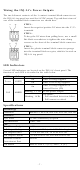
Wiring the INJ-24’s Power Outputs
The two left-most contacts of the 3-contact terminal block connector on
the INJ-24’s top panel are used for 24 VDC output. Top and front views of
one of the terminal block connectors are shown here.
STEP 1:
Insert the negative/positive DC wires into the V
-
/V+
terminals.
STEP 2:
To keep the DC wires from pulling loose, use a small
flat
-blade screwdriver to tighten the wire-clamp
screws on the front of the terminal block connector.
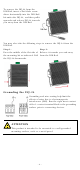
STEP 3:
Insert the plastic terminal block connector prongs
into the terminal block receptor, which is located on
INJ
-24’s top panel.
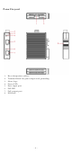
LED Indicators
Several LED indicators are located on the ING-24’s front panel. The
function of each LED is described in the table below.
LED
Color
State
Description
Power AMBER
On
Power is being supplied
Off
Power is not being supplied
PoE AMBER
On
Power is being supplied to a
Powered Device (PD)
Blinking, 1.5 Hz
No PoE power output
Blinking, 10 Hz
PoE failure:
1. PoE standard detection failure
2. PoE current overload
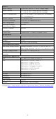
Specifications
Technology
Standards
IEEE802.3, 802.3u, 802.3ab, 802.3af, 802.3at
Interface
RJ45 Ports
10/100/1000BaseT(X) speed
LED Indicators
Power, PoE
PoE
Total Power Budget
30 W
PoE Output Voltage
50 @ 24/48 VDC (with full PoE loading)
PoE Output Power
15.4 W for 802.3af, 30 W for 802.3at
PoE Output Current
350 mA for 802.3af, 600 mA for 802.3at
Overload Current
Protection at Port
Present
PoE Pinout
Mode B: Pair 4, 5 (V+); Pair 7, 8 (V-)