IMC-21A Hardware Installation Guide Moxa Industrial Media Converter Third Edition, June 2012 2012 Moxa Inc. All rights reserved. Reproduction without permission is prohibited.
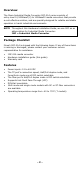
Overview The Moxa Industrial Media Converter IMC-21A series consists of entry-level 10/100BaseT(X) to 100BaseFX media converters that provide a cost-effective solution, and are specially designed for reliable and stable operation in harsh industrial environments. NOTE Throughout this Hardware Installation Guide, we use IMC as an abbreviation for Industrial Media Converter: IMC = Industrial Media Converter Package Checklist Moxa’s IMC-21A is shipped with the following items.
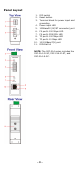
Panel Layout 1. 2. 3. 4. 5. 6. 7. 8. 9. 10. 11. DIP switch Reset button Terminal block for power input and grounding Power input LED 100BaseFX (SC/ST connector) port FX port's 100 Mbps LED FX port's FDX/COL LED TP port’s 100 Mbps LED TP port's 10 Mbps LED 10/100BaseT(X) port DIN-Rail kit NOTE: The IMC-21A series includes the IMC-21A-M-SC, IMC-21A-M-ST, and IMC-21A-S-SC.
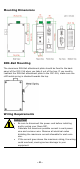
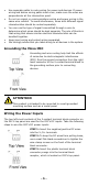
Mounting Dimensions DIN-Rail Mounting The aluminum DIN-Rail attachment plate should be fixed to the back panel of the IMC-21A when you take it out of the box. If you need to reattach the DIN-Rail attachment plate to the IMC-21A, make sure the stiff metal spring is situated towards the top. Wiring Requirements Safety First! • • • Be sure to disconnect the power cord before installing and/or wiring your Moxa IMC. Calculate the maximum possible current in each power wire and common wire.
• • • • • Use separate paths to route wiring for power and devices. If power wiring and device wiring paths must cross, make sure the wires are perpendicular at the intersection point. Do not run signal or communications wiring and power wiring in the same wire conduit. To avoid interference, wires with different signal characteristics should be routed separately. You can use the type of signal transmitted through a wire to determine which wires should be kept separate.
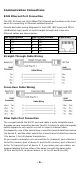
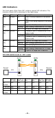
Communication Connections RJ45 Ethernet Port Connection The IMC-21A has one 10/100BaseT(X) Ethernet port located on the front panel for connecting to Ethernet-enabled devices.
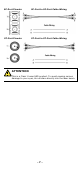
SC-Port Pinouts SC-Port to SC-Port Cable Wiring ST-Port Pinouts ST-Port to ST-Port Cable Wiring ATTENTION This is a Class 1 Laser/LED product. To avoid causing serious damage to your eyes, do not stare directly into the laser beam.
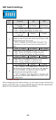
DIP Switch Settings DIP No. 1 2 3 4 Function ON OFF Force Fiber Port Full Duplex* Half Duplex Duplex “ON”: Forces Full Duplex on Fiber port. “OFF”: Forces Half Duplex on Fiber port. Link Fault Pass Enable* Disable Through “ON”: Enables “Link Fault Pass Through”, the link status on the TX port will inform the FX port of the same device and vice versa. “OFF”: Disables “Link Fault Pass Through”, the link status on the TX port will not inform the FX port.
LED Indicators The front panel of the Moxa IMC contains several LED indicators. The function of each LED is described in the table below. LED PWR Color AMBER State On Off 100M (FX) GREEN FDX/COL GREEN (FX) On Blinking Off On Blinking Off 100M (TP) GREEN 10M (TP) GREEN On Blinking Off On Blinking Off Description Power is being supplied to the power input. Power is not being supplied to the power input. FX port’s 100 Mbps link is active. Data is being transmitted at 100 Mbps.
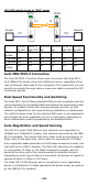
LFP: DIP switch is set to “DIS” mode DUTB DUTA F1 Device1 F2 TP1 Device1 TP LED OFF TP1 Faulted F1 Faulted ON F2 Faulted ON TP2 ON Faulted TP2 Device2 DUTA TP DUTA FO DUTB FO DUTB TP Device 2 LNK LED LED LED LNK LED TP LED OFF ON ON ON ON ON ON ON OFF OFF ON OFF OFF ON ON ON OFF ON ON OFF Auto MDI/MDI-X Connection The Auto MDI/MDI-X function allows users to connect the Moxa IMC’s 10/100BaseT(X) ports to any kind of Ethernet device, regardless of the type of Ethernet cable used for the connecti
Specifications Technology Standards Interface RJ45 Port Fiber Port LED Indicators DIP Switch IEEE802.3, 802.3u, 802.
Shock Free Fall Vibration Warranty IEC 60068-2-27 IEC 60068-2-32 IEC 60068-2-6 5 years Federal Communications Commission Statement FCC—This device complies with part 15 of the FCC Rules. Operation is subject to the following two conditions: (1) This device may not cause harmful interference, and (2) this device must accept any interference received, including interference that may cause undesired operation.