
User Manual


- 3 -
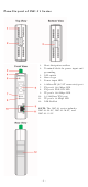
Panel Layout of IMC-21 Series
1.
Heat dissipation orifices
2.
Terminal block for power input and
grounding
3. DIP switch
4. Moxa Logo
5. Power input LED
6. 100BaseFX (SC/ST connector) port
7. FX port’s 100 Mbps LED
8. FX port’s FDX/COL LED
9. TP port’s 100 Mbps LED
10. 10/100BaseT(X) port
11. TP port’s 10 Mbps LED
12. DIN-Rail kit
NOTE: The IMC-21 series includes
IMC-21-M-SC, IMC-21-M-ST, and
IMC-21-S-SC.