IMC-21 Quick Installation Guide Moxa Industrial Media Converter Edition 5.0, February 2017 Technical Support Contact Information www.moxa.
Overview The Moxa Industrial Media Converter IMC-21 series consists of entry-level 10/100BaseT(X) to 100BaseFX media converters that provide a cost-effective solution, and are specially designed for reliable and stable operation in harsh industrial environments. IMC-21 accepts either a 12 to 48 VDC power input. It operates reliably in a temperature range from -10 to 60°C, and IMC-21’s rugged hardware design makes it ideal for demanding industrial applications, such as those that comply with FCC, CE.
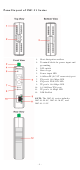
Panel Layout of IMC-21 Series 1. 2. 3. 4. 5. 6. 7. 8. 9. 10. 11. 12. Heat dissipation orifices Terminal block for power input and grounding DIP switch Moxa Logo Power input LED 100BaseFX (SC/ST connector) port FX port’s 100 Mbps LED FX port’s FDX/COL LED TP port’s 100 Mbps LED 10/100BaseT(X) port TP port’s 10 Mbps LED DIN-Rail kit NOTE: The IMC-21 series includes IMC-21-M-SC, IMC-21-M-ST, and IMC-21-S-SC.
Mounting Dimensions IMC-21 series (10/100BaseT(X) to 100BaseFX) DIN-Rail Mounting The plastic DIN-Rail attachment plate should already be fixed to the rear panel of IMC when you take it out of the box. If you need to reattach the DIN-Rail attachment plate to IMC, make sure the DIN-Rail kit is situated towards the top, as shown in the figures below. STEP 1: STEP 2: Insert the top of the DIN-Rail into The DIN-Rail attachment unit will the slot. snap into place as shown below.
Wiring Requirements ATTENTION Safety First! Be sure to disconnect the power cord before installing and/or wiring your Moxa Industrial Media Converter. Calculate the maximum possible current in each power wire and common wire. Observe all electrical codes dictating the maximum current allowable for each wire size. If the current goes above the maximum rating, the wiring could overheat, causing serious damage to your equipment.
Wiring the Power Inputs The two left-most contacts of the 3-contact terminal block connector on IMC’s top panel are used for IMC’s DC or AC inputs. Top and front views of one of the terminal block connectors are shown here. STEP 1: Insert the negative/positive DC wires into the V-/V+ terminals. Top View Front View STEP 2: To keep the DC wires from pulling loose, use a small flat-blade screwdriver to tighten the wire-clamp screws on the front of the terminal block connector.
RJ45 (8-pin) to RJ45 (8-pin) Cross-Over Cable Wiring Fiber Optical Port Connection The concept behind the SC/ST port and cable is quite straightforward. Suppose you are connecting devices I and II. Contrary to electrical signals, optical signals do not require a circuit in order to transmit data. Consequently, one of the optical lines is used to transmit data from device I to device II, and the other optical line is used transmit data from device II to device I, for full-duplex transmission.
DIP Switch Settings IMC-21 Series (10/100BaseT(X) to 100BaseFX) DIP Switch 1 (Default OFF: FDX) FDX: Fiber port in full duplex mode HDX: Fiber port in half duplex mode DIP Switch 2 (Default OFF: LFP) LFP: Enables LFP (Link Fault Pass-Through) for 100BaseFX LFP DIS: Disables LFP for 100BaseFX DIP Switch 3 (Default OFF: FDX) FDX: TP port at full duplex mode HDX: TP port at half duplex mode DIP Switch 4 (Default OFF: 100) 100: TP port at 100 Mbps 10: TP port at 10 Mbps DIP Switch 5 (Default OFF: AUTO) AUTO: T
LFP DIP switch is set to “LFP” mode: Device1 TP LED OFF TP1 Faulted F1 Faulted OFF F2 Faulted OFF TP2 OFF Faulted DUTA TP DUTA FO DUTB FO DUTB TP Device 2 LNK LED LED LED LNK LED TP LED OFF OFF OFF OFF OFF OFF OFF OFF OFF OFF OFF OFF OFF OFF OFF OFF OFF OFF OFF OFF LFP DIP switch is set to “DIS” mode: Device1 TP LED OFF TP1 Faulted F1 Faulted ON F2 Faulted ON TP2 ON Faulted DUTA TP DUTA FO DUTB FO DUTB TP Device 2 LNK LED LED LED LNK LED TP LED OFF ON ON ON ON ON ON ON OFF OFF ON OFF OFF ON ON
Dual Speed Functionality and Switching Moxa Industrial Media Converter’s 10/100 Mbps switched RJ45 port auto negotiates with the connected device for the fastest data transmission rate supported by both devices. All models of Moxa Industrial Media Converter are plug-and-play devices, so that software configuration is not required during installation, or for maintenance.
Power Input Voltage Power Consumption Connection Overload Current Protection Reverse Polarity Protection Mechanical Casing Dimensions Weight Installation Environmental Operating Temperature Storage Temperature Ambient Relative Humidity Regulatory Approvals Safety EMI EMS Shock Free Fall Vibration Warranty 12 to 48 VDC M-SC/ST: 271 mA @ 12 V 137 mA @ 24 V 77 mA @ 48 V Removable 3-contact 1.