
Installation guide

- 9 -
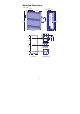
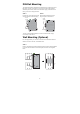
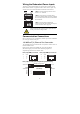
Wiring the Redundant Power Inputs
The top two contacts and the bottom two contacts of the 6-contact terminal
block connector on IMC’s top panel are used for IMC’s two DC inputs. Top
and front views of one of the terminal block connectors are shown here.
Top View
Front View
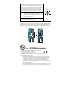
STEP 1: Insert the negative/positive DC wires
into the V-/V+ terminals.
STEP 2: To keep the DC wires from pulling
loose, use a small flat-
b
lade screwdriver to tighten
the wire-clamp screws on the front of the terminal
block connector.
STEP 3: Insert the plastic terminal block
connector prongs into the terminal block receptor,
which is located on IMC’s top panel.
ATTENTION
Before connecting IMC to the DC power inputs, make sure
the DC power source voltage is stable.
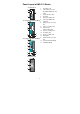
Communication Connections
IMC-101 models have one 10/100BaseT(X) Ethernet port, and one 100BaseFX
(SC or ST type connector) fiber port.
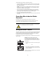
10/100BaseT(X) Ethernet Port Connection
The 10/100BaseT(X) ports located on IMC’s front panel are used to connect to
Ethernet-enabled devices.
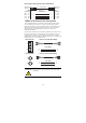
Below we show pinouts for both MDI (NIC-type) ports and MDI-X
(HUB/Switch-type) ports, and also show cable wiring diagrams for
straight-through and cross-over Ethernet cables.
RJ45 (8-pin, MDI) Port Pinouts RJ45 (8-pin, MDI-X) Port Pinouts
1
8
Pin Signal
1
2
3
6
Tx+
Tx-
Rx+
Rx-
1
8
Pin Signal
1
2
3
6
Rx+
Rx-
Tx+
Tx-
RJ45 (8-pin) to RJ45 (8-pin) Straight-Through Cable Wiring
Straight-Through Cable
RJ45 Plug Pin 1
Switch Port
RJ45
Connector
RJ45
Connecto
r
Tx+
Tx-
Rx+
Rx-
NIC Port
Cable Wiring
3 3
6 6
1 1
2 2
Rx+
Rx-
Tx+
Tx-