Moxa Industrial Media Converter IMC-101 Hardware Installation Guide Fifth Edition, April 2010 2010 Moxa Inc. All rights reserved. Reproduction without permission is prohibited. Fl.4, No.135, Lane 235, Pao-Chiao Rd. Shing Tien City, Taipei, Taiwan, R.O.C.
Overview Moxa Industrial Media Converter, which is specially designed for reliable and stable operation in harsh industrial environments, provides industrial grade media conversion between 10/100BaseT(X) and 100BaseFX. IMC-101’s reliable industrial design is excellent for keeping your industrial automation applications running continuously, and comes with a relay output warning alarm to help prevent damages and losses.
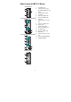
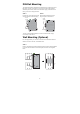
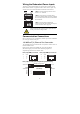
Panel Layout of IMC-101 Series Top Panel View 1 2 1. 2. V2+ Grounding screw Terminal block for power PWR2 V2- input PWR1/PWR2 and relay FAULT V1+ PWR1 V1V1 V2 INPUTS: 24 VDC 3 output 3. Heat dissipation orifices PORT ALARM 1 ON 2 3 DIP 4 4. Dip switch 5. Power input PWR1 LED Front Panel View (IMC-101-M-ST) 6. 7. 2 5 8. 6 7 9. 8 10. 9 10 11. FDX/COL 12.
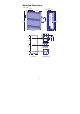
Mounting Dimensions (Unit = mm) 15.10 30.00 13.10 54.00 9.50 25.40 135.00 135.00 Side View Front View 13.90 18.20 13.90 3.5 6 3.5 6 25.71 + + + + 7.75 39.37 + + + + + 6 + + + 13 30.50 18 13 + + + + + + 66.80 10 57.05 10 5 7.75 46.77 + + 23.15 + + + + 30.50 10.65 10.
DIN-Rail Mounting The aluminum DIN-Rail attachment plate should be fixed to the back panel of IMC when you take it out of the box. If you need to reattach the DIN-Rail attachment plate to IMC, make sure the stiff metal spring is situated towards the top, as shown in the figures below. STEP 1: STEP 2: Insert the top of the DIN-Rail into the The DIN-Rail attachment unit will slot just below the stiff metal spring. snap into place as shown below.
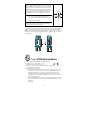
STEP 2: Mounting Moxa Industrial Media Converter on the wall requires 4 screws. Use the IMC, with wall mount plates attached, as a guide to mark the correct locations of the 4 screws. The heads of the screws should be less than 6.0 mm in diameter, and the shafts should be less than 3.5 mm in diameter, as shown in the figure at the right. NOTE Test the screw head and shank size by inserting the screw into one of the keyhole shaped apertures of the Wall Mounting Plates, before it is screwed into the wall. 6.
Wiring Requirements WARNING Do not disconnect modules or wires unless power has been switched off or the area is known to be non hazardous. The devices may only be connected to the supply voltage shown on the type plate. The devices are designed for operation with a safety extra-low voltage. Thus, they may only be connected to the supply voltage connections and to the signal contact with the safety extra-low voltages (SELV) in compliance with IEC950/ EN60950/ VDE0805.
You should also pay attention to the following points: Use separate paths to route wiring for power and devices. If power wiring and device wiring paths must cross, make sure the wires are perpendicular at the intersection point. NOTE: Do not run signal or communications wiring and power wiring in the same wire conduit. To avoid interference, wires with different signal characteristics should be routed separately.
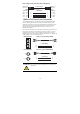
Wiring the Redundant Power Inputs The top two contacts and the bottom two contacts of the 6-contact terminal block connector on IMC’s top panel are used for IMC’s two DC inputs. Top and front views of one of the terminal block connectors are shown here. STEP 1: Insert the negative/positive DC wires into the V-/V+ terminals. Top View STEP 2: To keep the DC wires from pulling loose, use a small flat-blade screwdriver to tighten the wire-clamp screws on the front of the terminal block connector.
RJ45 (8-pin) to RJ45 (8-pin) Cross-Over Cable Wiring Cross-Over Cable Switch Port (NIC Port) RJ45 Plug Pin 1 RJ45 Connector (Rx+) (Rx-) (Tx+) (Tx-) Tx+ TxRx+ Rx- Switch Port (NIC Port) RJ45 Connector Cable Wiring 3 6 1 2 1 2 3 6 Rx+ RxTx+ Tx- (Tx+) (Tx-) (Rx+) (Rx-) 100BaseFX Ethernet Port Connection The concept behind the SC port and cable is quite straightforward. Suppose you are connecting devices I and II.
Redundant Power Inputs Both power inputs can be connected simultaneously to live DC power sources. If one power source fails, the other live source acts as a backup, and automatically supplies all of Moxa Industrial Media Converter’s power needs. Alarm Contact Moxa Industrial Media Converter has one Alarm Contact located on the top panel.
LED Indicators The front panel of Moxa Industrial Media Converter contains several LED indicators. The function of each LED is described in the table below. LED PWR1 PWR2 FAULT 10M 100M (TP) 100M (FX) FDX/ COL Color State On Off Power is not being supplied to power input PWR1 On Power is being supplied to power input PWR2 Off Power is not being supplied to power input PWR2 On When the corresponding PORT alarm is enabled, and the port’s link is inactive.
Auto MDI/MDI-X Connection The Auto MDI/MDI-X function allows users to connect Moxa Industrial Media Converter’s 10/100BaseTX ports to any kind of Ethernet device, without paying attention to the type of Ethernet cable being used for the connection. This means that you can use either a straight-through cable or cross-over cable to connect IMC to Ethernet devices.
Specifications Technology Standards Interface RJ45 ports Fiber ports LED Indicators Dip Switch Alarm Contact IEEE802.3, 802.
Shock Free Fall Vibration WARRANTY EN61000-4-3 (RS), level 3 EN61000-4-4 (EFT), level 3 EN61000-4-5 (Surge), level 2 EN61000-4-2 (CS), level 3 IEC 60068-2-27 IEC 60068-2-32 IEC 60068-2-6 5 years Revision History Document Edition Revision Date 2nd June 15, 2004 Revision Details 1. Updated the edition of this manual on the title page. 2. Changed the Moxa logo on the title page. 3. Added several “Attention” messages 4.
Serial Number The serial number of a product is made up of 12 alphanumeric characters and includes the region in which the product was manufactured, the year and month the product was manufactured, the product category, and the production number. Position in Serial Number Meaning Possible Values Example(s) 1 Production 0 to 9, or “T” means Taiwan Region D to Z 2 and 3 Year Z = 0, A = 1, B = 2, ...... I = 9 4 Month A = JAN, B = FEB, C = MAR, ......