
User`s manual


IKS-6726 Featured Functions
3-21
Select two ports on each switch to be used as coupling ports and link them together. Next, assign one switch
(e.g., Switch A) to be the coupler and connect the coupler’s coupling control port with Switch B (for this
example).
The coupler switch (i.e., Switch A) will monitor switch B through the coupling control port to determine whether
or not the coupling port’s backup path should be recovered.
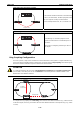
Ring Coupling for Turbo Ring V2
Switch B
Switch A
Switch D
Switch C
Main Path
Coupling Port (Primary)
Coupling Port (Backup)
Backup Path
13
24
57
68
13
5
5
TX RX
6
24
M3
M2M1
IKS-6726
1
TX RX
2
TX RX
STAT
FAULT
PWR1
MASTER
PWR2
COUPLER
LNK/ACT SPEED FDX/HDX
RING PORT
COMUPLER
PORT
MODE
1
3
24
57
68
M1
M2
M3
13
24
57
68
13
5
5
TX RX
6
24
M3
M2M1
IKS-6726
1
TX RX
2
TX RX
STAT
FAULT
PWR1
MASTER
PWR2
COUPLER
LNK/ACT SPEED FDX/HDX
RING PORT
COMUPLER
PORT
MODE
1
3
24
57
68
M1
M2
M3
13
24
57
68
13
5
5
TX RX
6
24
M3
M2M1
IKS-6726
1
TX RX
2
TX RX
STAT
FAULT
PWR1
MASTER
PWR2
COUPLER
LNK/ACT SPEED FDX/HDX
RING PORT
COMUPLER
PORT
MODE
1
3
24
57
68
M1
M2
M3
13
24
57
68
13
5
5
TX RX
6
24
M3
M2M1
IKS-6726
1
TX RX
2
TX RX
STAT
FAULT
PWR1
MASTER
PWR2
COUPLER
LNK/ACT SPEED FDX/HDX
RING PORT
COMUPLER
PORT
MODE
1
3
24
57
68
M1
M2
M3
13
24
57
68
13
5
5
TX RX
6
24
M3
M2M1
IKS-6726
1
TX RX
2
TX RX
STAT
FAULT
PWR1
MASTER
PWR2
COUPLER
LNK/ACT SPEED FDX/HDX
RING PORT
COMUPLER
PORT
MODE
1
3
24
57
68
M1
M2
M3
13
24
57
68
13
5
5
TX RX
6
24
M3
M2M1
IKS-6726
1
TX RX
2
TX RX
STAT
FAULT
PWR1
MASTER
PWR2
COUPLER
LNK/ACT SPEED FDX/HDX
RING PORT
COMUPLER
PORT
MODE
1
3
24
57
68
M1
M2
M3
Note that the ring coupling settings for a Turbo Ring V2 are different from a Turbo Ring. For Turbo Ring V2,
ring coupling is enabled by configuring the Coupling Port (Primary) on Switch B and the Coupling Port
(Backup) on Switch A only. You do not need to set up a coupling control port, so Turbo Ring V2 does not
require a coupling control line.
The Coupling Port (Backup) on Switch A is used for the backup path and connects directly to a network port
on Switch C. The Coupling Port (Primary) on Switch B monitors the status of the main path, and connects
directly to an extra network port on Switch D. With ring coupling established, Switch A can activate the backup
path as soon as it detects a problem with the main path.
ATTENTION
Ring coupling only needs to be enabled on one of the switches serving as the ring coupler. The coupler must
assign separate ports for the two Turbo Ring ports and the coupling port.
NOTE You do not need to use the same IKS series Ethernet switch for both ring coupling and ring master.
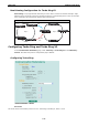
Dual-Ring Configuration (applies only to “Turbo Ring V2”)
The “dual-ring” option, in which two adjacent rings share one switch, provides another ring coupling
configuration. This type of configuration is ideal for applications that have inherent cabling difficulties.
Ring A
Master
Master
Ring B
13
24
57
68
13
5
5
TX RX
6
24
M3
M2
M1
IKS-6726
1
TX RX
2
TX RX
STAT
FAULT
PWR1
MASTER
PWR2
COUPLER
LNK/ACT SPEED FDX/HDX
RING PORT
COMUPLER
PORT
MODE
1
3
24
57
68
M1
M2
M3
13
24
57
68
13
5
5
TX RX
6
24
M3
M2
M1
IKS-6726
1
TX RX
2
TX RX
STAT
FAULT
PWR1
MASTER
PWR2
COUPLER
LNK/ACT SPEED FDX/HDX
RING PORT
COMUPLER
PORT
MODE
13
24
57
68
M1
M2
M3
13
24
57
68
13
5
5
TX RX
6
24
M3
M2
M1
IKS-6726
1
TX RX
2
TX RX
STAT
FAULT
PWR1
MASTER
PWR2
COUPLER
LNK/ACT SPEED FDX/HDX
RING PORT
COMUPLER
PORT
MODE
1
3
24
57
68
M1
M2
M3
13
24
57
68
13
5
5
TX RX
6
24
M3
M2
M1
IKS-6726
1
TX RX
2
TX RX
STAT
FAULT
PWR1
MASTER
PWR2
COUPLER
LNK/ACT SPEED FDX/HDX
RING PORT
COMUPLER
PORT
MODE
13
24
57
68
M1
M2
M3
13
24
57
68
13
5
5
TX RX
6
24
M3
M2
M1
IKS-6726
1
TX RX
2
TX RX
STAT
FAULT
PWR1
MASTER
PWR2
COUPLER
LNK/ACT SPEED FDX/HDX
RING PORT
COMUPLER
PORT
MODE
13
24
57
68
M1
M2
M3