
User`s manual


IKS-6726 Featured Functions
3-20
Turbo Ring with odd number switches
13
24
57
68
13
5
5
TX RX
6
24
M3
M2
M1
IKS-6726
1
TX RX
2
TX RX
STAT
FAULT
PWR1
MASTER
PWR2
COUPLER
LNK/ACT SPEED FDX/HDX
RING PORT
COMUPLER
PORT
MODE
1
3
24
57
68
M1
M2
M3
13
24
57
68
13
5
5
TX RX
6
24
M3
M2
M1
IKS-6726
1
TX RX
2
TX RX
STAT
FAULT
PWR1
MASTER
PWR2
COUPLER
LNK/ACT SPEED FDX/HDX
RING PORT
COMUPLER
PORT
MODE
1
3
24
57
68
M1
M2
M3
13
24
57
68
13
5
5
TX RX
6
24
M3
M2
M1
IKS-6726
1
TX RX
2
TX RX
STAT
FAULT
PWR1
MASTER
PWR2
COUPLER
LNK/ACT SPEED FDX/HDX
RING PORT
COMUPLER
PORT
MODE
1
3
24
57
68
M1
M2
M3
Segment N+1
Master
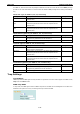
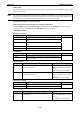
If the number of Ethernet switches in the Turbo Ring
is 2N+1 (an odd number), the backup segment is the
(N+1)st segment counting counterclockwise.
For the example shown here, N=1, so that N+1=2.
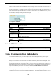
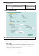
Determining the Redundant Path for Turbo Ring V2
13
24
57
68
13
5
5
TX RX
6
24
M3
M2
M1
IKS-6726
1
TX RX
2
TX RX
STAT
FAULT
PWR1
MASTER
PWR2
COUPLER
LNK/ACT SPEED FDX/HDX
RING PORT
COMUPLER
PORT
MODE
1
3
24
57
68
M1
M2
M3
13
24
57
68
13
5
5
TX RX
6
24
M3
M2
M1
IKS-6726
1
TX RX
2
TX RX
STAT
FAULT
PWR1
MASTER
PWR2
COUPLER
LNK/ACT SPEED FDX/HDX
RING PORT
COMUPLER
PORT
MODE
1
3
24
57
68
M1
M2
M3
13
24
57
68
13
5
5
TX RX
6
24
M3
M2
M1
IKS-6726
1
TX RX
2
TX RX
STAT
FAULT
PWR1
MASTER
PWR2
COUPLER
LNK/ACT SPEED FDX/HDX
RING PORT
COMUPLER
PORT
MODE
1
3
24
57
68
M1
M2
M3
13
24
57
68
13
5
5
TX RX
6
24
M3
M2
M1
IKS-6726
1
TX RX
2
TX RX
STAT
FAULT
PWR1
MASTER
PWR2
COUPLER
LNK/ACT SPEED FDX/HDX
RING PORT
COMUPLER
PORT
MODE
1
3
24
57
68
M1
M2
M3
Master
For Turbo Ring V2, the backup segment is the
segment connected to the 2nd redundant port on
the master.
Please refer to Configuring Turbo Ring V2 later in
this chapter.
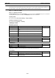
Ring Coupling Configuration
For some systems, it may not be convenient to connect all devices in the system in a single redundant ring,
since some devices could be located in a remote area. For these systems, Ring Coupling can be used to group
devices into smaller redundant rings that communicate with each other.
ATTENTION
In a VLAN environment, the user must set Redundant Port Coupling Port and Coupling Control Port to
join all VLANs, since these ports act as the backbone to transmit all packets of different VLANs to the
different IKS series Ethernet switches.
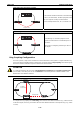
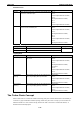
Ring Coupling for Turbo Ring
Switch B
Switch A: Coupler
Switch D
Switch C
Main Path
Coupling
Control Port
Coupling Port
Backup Path
13
24
57
68
13
5
5
TX RX
6
24
M3
M2M1
IKS-6726
1
TX RX
2
TX RX
STAT
FAULT
PWR1
MASTER
PWR2
COUPLER
LNK/ACT SPEED FDX/HDX
RING PORT
COMUPLER
PORT
MODE
1
3
24
57
68
M1
M2
M3
13
24
57
68
13
5
5
TX RX
6
24
M3
M2M1
IKS-6726
1
TX RX
2
TX RX
STAT
FAULT
PWR1
MASTER
PWR2
COUPLER
LNK/ACT SPEED FDX/HDX
RING PORT
COMUPLER
PORT
MODE
1
3
24
57
68
M1
M2
M3
13
24
57
68
13
5
5
TX RX
6
24
M3
M2M1
IKS-6726
1
TX RX
2
TX RX
STAT
FAULT
PWR1
MASTER
PWR2
COUPLER
LNK/ACT SPEED FDX/HDX
RING PORT
COMUPLER
PORT
MODE
1
3
24
57
68
M1
M2
M3
13
24
57
68
13
5
5
TX RX
6
24
M3
M2M1
IKS-6726
1
TX RX
2
TX RX
STAT
FAULT
PWR1
MASTER
PWR2
COUPLER
LNK/ACT SPEED FDX/HDX
RING PORT
COMUPLER
PORT
MODE
1
3
24
57
68
M1
M2
M3
13
24
57
68
13
5
5
TX RX
6
24
M3
M2M1
IKS-6726
1
TX RX
2
TX RX
STAT
FAULT
PWR1
MASTER
PWR2
COUPLER
LNK/ACT SPEED FDX/HDX
RING PORT
COMUPLER
PORT
MODE
1
3
24
57
68
M1
M2
M3
13
24
57
68
13
5
5
TX RX
6
24
M3
M2M1
IKS-6726
1
TX RX
2
TX RX
STAT
FAULT
PWR1
MASTER
PWR2
COUPLER
LNK/ACT SPEED FDX/HDX
RING PORT
COMUPLER
PORT
MODE
1
3
24
57
68
M1
M2
M3
To configure the ring coupling for a Turbo Ring, select two IKS series Ethernet switches (e.g., Switch A and B
in the above figure) in the ring, and another two IKS series Ethernet switches in the adjacent ring (e.g., Switch
C and D).