
User`s manual


IKS-6726 Featured Functions
3-19
following table lists the key differences between each feature. Use this information to evaluate each the
benefits of each, and then determine which features are most suitable for your network.
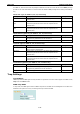
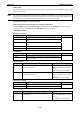
Turbo Ring V2 Turbo Ring STP RSTP
Topology Ring Ring Ring, Mesh Ring, Mesh
Recovery Time < 20 ms < 300 ms Up to 30 sec. Up to 5 sec
NOTE Most managed switches by Moxa support two proprietary Turbo Ring protocols:
• Turbo Ring refers to the original version of Moxa’s proprietary redundant ring protocol, which has a
recovery time of under 300 ms.
• Turbo Ring V2 refers to the new generation Turbo Ring, which has a recovery time of under 20 ms.
The Turbo Ring Concept
Moxa developed the proprietary Turbo Ring protocol to optimize communication redundancy and achieve a
faster recovery time on the network.
The Turbo Ring and Turbo Ring V2 protocols designate one switch as the master of the network, and then
automatically block packets from traveling through any of the network’s redundant loops. In the event that one
branch of the ring gets disconnected from the rest of the network, the protocol automatically readjusts the ring
so that the part of the network that was disconnected can reestablish contact with the rest of the network.
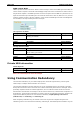
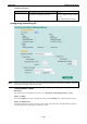
Initial setup for Turbo Ring or Turbo Ring V2
13
24
57
68
13
5
5
TX RX
6
24
M3
M2
M1
IKS-6726
1
TX RX
2
TX RX
STAT
FAULT
PWR1
MASTER
PWR2
COUPLER
LNK/ACT SPEED FDX/HDX
RING PORT
COMUPLER
PORT
MODE
1
3
24
57
68
M1
M2
M3
13
24
57
68
13
5
5
TX RX
6
24
M3
M2
M1
IKS-6726
1
TX RX
2
TX RX
STAT
FAULT
PWR1
MASTER
PWR2
COUPLER
LNK/ACT SPEED FDX/HDX
RING PORT
COMUPLER
PORT
MODE
1
3
24
57
68
M1
M2
M3
13
24
57
68
13
5
5
TX RX
6
24
M3
M2
M1
IKS-6726
1
TX RX
2
TX RX
STAT
FAULT
PWR1
MASTER
PWR2
COUPLER
LNK/ACT SPEED FDX/HDX
RING PORT
COMUPLER
PORT
MODE
1
3
24
57
68
M1
M2
M3
1. For each switch in the ring, select any two ports
as the redundant ports.
2. Connect redundant ports on neighboring
switches to form the redundant ring.
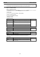
The user does not need to manually assign the master with Turbo Ring or Turbo Ring V2. If no switch is
assigned as the master, the protocol automatically selects one of the switches to be the master. The master is
only used to identify which segment in the redundant ring acts as the backup path. In the following subsections,
we explain how the redundant path is selected for rings configured for Turbo Ring and Turbo Ring V2.
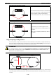
Determining the Redundant Path for Turbo Ring
In this case, the redundant segment (i.e., the segment that will be blocked during normal operation) is
determined by the number of IKS series Ethernet switches in the ring and by the location of the master switch.
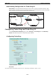
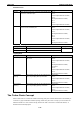
Turbo Ring with even number of switches
13
24
57
68
13
5
5
TX RX
6
24
M3
M2
M1
IKS-6726
1
TX RX
2
TX RX
STAT
FAULT
PWR1
MASTER
PWR2
COUPLER
LNK/ACT SPEED FDX/HDX
RING PORT
COMUPLER
PORT
MODE
1
3
24
57
68
M1
M2
M3
13
24
57
68
13
5
5
TX RX
6
24
M3
M2
M1
IKS-6726
1
TX RX
2
TX RX
STAT
FAULT
PWR1
MASTER
PWR2
COUPLER
LNK/ACT SPEED FDX/HDX
RING PORT
COMUPLER
PORT
MODE
1
3
24
57
68
M1
M2
M3
13
24
57
68
13
5
5
TX RX
6
24
M3
M2
M1
IKS-6726
1
TX RX
2
TX RX
STAT
FAULT
PWR1
MASTER
PWR2
COUPLER
LNK/ACT SPEED FDX/HDX
RING PORT
COMUPLER
PORT
MODE
1
3
24
57
68
M1
M2
M3
13
24
57
68
13
5
5
TX RX
6
24
M3
M2
M1
IKS-6726
1
TX RX
2
TX RX
STAT
FAULT
PWR1
MASTER
PWR2
COUPLER
LNK/ACT SPEED FDX/HDX
RING PORT
COMUPLER
PORT
MODE
1
3
24
57
68
M1
M2
M3
Master
If the number of Ethernet switches in the Turbo Ring
is 2N (an even number), the backup segment is one
of the two segments connected to the (N+1) st
switch (i.e., the unit directly opposite the master).