Moxa Industrial Rackmount Switch IKS-6726 User’s Manual Second Edition, June 2010 www.moxa.com/product © 2010 Moxa Inc. All rights reserved. Reproduction without permission is prohibited.
Moxa Industrial Rackmount Switch IKS-6726 User’s Manual The software described in this manual is furnished under a license agreement and may be used only in accordance with the terms of that agreement. Copyright Notice Copyright ©2010 Moxa Inc. All rights reserved. Reproduction without permission is prohibited. Trademarks The MOXA logo is a registered trademark of Moxa Inc. All other trademarks or registered marks in this manual belong to their respective manufacturers.
Table of Contents 1. Introduction...................................................................................................................................... 1-1 Overview ...........................................................................................................................................1-2 Package Checklist ...............................................................................................................................1-2 Software Features ....................
Using Set Device IP........................................................................................................................... 3-62 Configuring Set Device IP ........................................................................................................... 3-63 DHCP Option 82 ........................................................................................................................ 3-63 Using Diagnosis ....................................................................
1 1. Introduction Welcome to the IKS-6726, a managed redundant Gigabit Ethernet switch designed especially for connecting Ethernet-enabled devices for industrial field applications.
IKS-6726 Introduction Overview The IKS-6726 is certified for use in maritime applications (DNV/GL), traffic control systems (NEMA TS 2), and railway applications (EN50121-4). It can be used for Gigabit or Fast Ethernet backbones and supports redundant ring topologies. It also supports dual power inputs (24/48 VDC or 110/220 VDC/VAC) to increase the reliability of communication. The IKS-6726 has a modular design that makes network planning easy and allows greater flexibility.
2 2. Getting Started This chapter explains how the initial installation process for the IKS-6726. There are three ways to access IKS-6726’s configuration settings: the serial console, Telnet console, and web console. If you do not know the IKS-6726’s IP address, you can open the serial console by connecting the IKS-6726 to a PC’s COM port with a short serial cable. You can open the Telnet or web console over an Ethernet LAN or over the Internet.
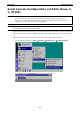
IKS-6726 Gettying Started Serial Console Configuration (115200, None, 8, 1, VT100) NOTE • You cannot connect to the serial and Telnet console at the same time. • You can connect to the web console and another console (serial or Telnet) at the same time. However, it is strongly recommended that you do NOT do so. Following this advice will allow you to maintain better control over the IKS-6726’s configuration. NOTE We recommend using PComm Terminal Emulator when opening the serial console.
IKS-6726 Gettying Started 3. The Property window should open. On the Communication Parameter tab for Ports, select the COM port that is being used for the console connection. Set the other fields as follows: 115200 for Baud Rate, 8 for Data Bits, None for Parity, and 1 for Stop Bits. 4. On the Terminal tab, select VT100 for Terminal Type. Click OK. 5. In the terminal window, the IKS-6726 will prompt you to select a terminal type. Enter 1 to select ansi/vt100 and press Enter.
IKS-6726 Gettying Started 6. The serial console will prompt you to log in. Press Enter and select admin or user. Use the down arrow key on your keyboard to select the Password field and enter a password if desired. This password will be required to access any of the consoles (web, serial, Telnet). If you do not wish to create a password, leave the Password field blank and press Enter. 7. The Main Menu of the IKS-6726’s serial console should appear.
IKS-6726 NOTE Gettying Started To connect to the IKS-6726’s Telnet or web console, your PC host and the IKS-6726 must be on the same logical subnet. NOTE When connecting to the IKS-6726’s Telnet or web console, first connect one of IKS-6726’s Ethernet ports to your Ethernet LAN or directly to your PC’s Ethernet port. You may use either a straight-through or cross-over Ethernet cable. NOTE The IKS-6726’s default IP address is 192.168.127.253.
IKS-6726 Gettying Started 4. The Main Menu of the IKS-6726’s Telnet console should appear. 5. In the terminal window, select Preferences… from the Terminal menu on the menu bar. 6. The Terminal Preferences window should appear. Make sure that VT100 Arrows is checked. 7.
IKS-6726 NOTE Gettying Started When connecting to the IKS-6726’s Telnet or web console, first connect one of IKS-6726’s Ethernet ports to your Ethernet LAN or directly to your PC’s Ethernet port. You may use either a straight-through or cross-over Ethernet cable. NOTE The IKS-6726’s default IP address is 192.168.127.253. After making sure that the IKS-6726 is connected to the same LAN and logical subnet as your PC, open the IKS-6726’s web console as follows: 1.
IKS-6726 Gettying Started Disabling Telnet and Browser Access If you are connecting the IKS-6726 to a public network but do not intend to manage it over the network, we suggest disabling both the Telnet and web consoles. This is done through the serial console, by navigating to System Identification under Basic Settings.
3 3. Featured Functions This chapter explains how to access IKS-6726’s various configuration, monitoring, and administration functions. These functions can be accessed by serial, Telnet, or web console. The serial console can be used if you do not know IKS-6726’s IP address and requires that you connect the IKS-6726 to a PC COM port. The Telnet and web consoles can be opened over an Ethernet LAN or the Internet. The web console is the most user-friendly way to configure IKS-6726.
IKS-6726 Featured Functions Configuring Basic Settings Basic Settings includes the most common settings required by administrators to maintain and control the IKS-6726. System Identification System Identification items are displayed at the top of the web console and will be included in alarm emails. You can set the System Identification items to make it easier to identify different switches that are connected to your network. Switch Name Setting Max.
IKS-6726 Featured Functions ATTENTION By default, no password is assigned to the IKS-6726’s web, Telnet, and serial consoles. If a password is assigned, you will be required to enter the password when you open the serial console, Telnet console, or Web console. Account Setting Description Factory Default Admin This account can modify the IKS-6726’s configuration. admin User This account can only view the IKS-6726’s configurations.
IKS-6726 • Featured Functions Grant access to one host with a specific IP address For example, enter IP address 192.168.1.1 with netmask 255.255.255.255 to allow access to 192.168.1.1 only. • Grant access to any host on a specific subnetwork For example, enter IP address 192.168.1.0 with netmask 255.255.255.0 to allow access to all IPs on the subnet defined by this IP address/subnet mask combination. • Grant acces to all hosts Make sure the accessible IP list is not enabled.
IKS-6726 Featured Functions Description Setting Description Factory Default Media type This displays the media type for each module’s port N/A Setting Description Factory Default Max. 63 characters This specifies an alias for the port to help administrators None Name differentiate between different ports. Example: PLC 1 Speed Setting Description Factory Default Auto This allows the port to use the IEEE 802.3u protocol to Auto negotiate with connected devices.
IKS-6726 Featured Functions Auto IP Configuration Setting Description Factory Default Disable Select this to set the IKS-6726’s IP address manually. Disable By DHCP The IKS-6726’s IP address will be assigned automatically by the network’s DHCP server. By BootP The IKS-6726’s IP address will be assigned automatically by the network’s BootP server. Switch IP Address Setting Description Factory Default IP address for the This assigns the IKS-6726’s IP address on a TCP/IP network. 192.168.127.
IKS-6726 Featured Functions Global Unicast Address Prefix (Prefix Length: 64 bits) Default Gateway Setting Description Factory Default Global Unicast Address The prefix value must be formatted according to the RFC 2373 None Prefix “IPv6 Addressing Architecture,” using 8 colon-separated 16-bit hexadecimal values. One double colon may be used in the address to indicate the appropriate number of zeros required to fill the undefined fields.
IKS-6726 NOTE Featured Functions The IKS-6726 does not have a real time clock. The user must update the Current Time and Current Date to set the initial time for IKS-6726 after each reboot, especially when there is no NTP server on the LAN or Internet connection. Current Time Setting Description Factory Default User-specified time This allows configuration of the local time in local 24-hour None format.
IKS-6726 Featured Functions IEEE 1588 PTP The following information is taken from the NIST website at http://ieee1588.nist.gov/intro.htm: ”Time measurement can be accomplished using the IEEE Standard for a Precision Clock Synchronization Protocol for Networked Measurement and Control Systems (IEEE 1588-2008) to synchronize real-time clocks incorporated within each component of the electrical power system for power automation applications.
IKS-6726 Featured Functions Operation IEEE 1588/PTP Setting Description Factory Default Operation Disable or enable IEEE 1588 (PTP) operation Disable Time Server Query Period Setting Description Factory Default Clock Mode Support software-based IEEE 1588 (PTP) mode Disable Sync Interval Interval for sending synchronization message (in seconds) Disable Sub-domain Name Support _DFLT (Default) domain only _DFLT Setting Description Factory Default Offset To Master (nsec) Deviation between
IKS-6726 Featured Functions TFTP Server IP/Name Setting Description Factory Default IP address of TFTP This specifies the IP address or name of the remote TFTP None server server. This must be specified before downloading or uploading files. Configuration Files Path and Name Setting Max. 40 characters Description Factory Default This specifies the path and file name of the IKS-6726’s None configuration file on the TFTP server.
IKS-6726 Featured Functions Log File Click Export to save the IKS-6726’s log file to the local host. NOTE Some operating systems will open the configuration file and log file directly in the web page. In such cases, right click the Export button to save the file. Upgrade Firmware To import a new firmware file onto the IKS-6726, click Browse to select the firmware file that is saved on your computer. The upgrade procedure will proceed automatically after clicking Import.
IKS-6726 Featured Functions Factory Default This function provides users with a quick way of restoring the IKS-6726’s configuration to factory defaults. This function is available in the serial, Telnet, and web consoles. NOTE After restoring the factory default configuration, you will need to use the default network settings to re-establish the web or Telnet console connection with the IKS-6726. Using Port Trunking Link aggregation involves grouping links to into a link aggregation group.
IKS-6726 Featured Functions Configuring Port Trunking The Port Trunking Settings page is where ports are assigned to a trunk group. Step 1: Select the desired Trunk Group (Trk1, Trk2, Trk3). Step 2: Select the Trunk Type (Static or LACP). Step 3: Select the desired ports under Available Ports and click Up to add to the Trunk Group. Step 4: Select the desired ports under Member Ports and click Down to remove from the group.
IKS-6726 Featured Functions Trunk Table Setting Description Trunk group Displays the trunk type and trunk group. Member port Displays the member ports that belong to the trunk group. Status Success means port trunking is working properly. Fail means port trunking is not working properly. Standby means port trunking is working as a standby port. When there are more than eight ports trunked as a trunking group, the 9th port will be the standby port.
IKS-6726 Featured Functions SNMP Read/Write Settings SNMP Versions Setting Description Factory Default V1, V2c, V3, or This specifies the SNMP protocol version used to manage the V1, V2c V1, V2c, or switch. V3 only V1, V2c Read Community Setting Description Factory Default Max. 30 characters This specifies the community string to authenticate the SNMP Public agent for read-only access. The SNMP agent will access all objects with read-only permissions using this community string.
IKS-6726 Featured Functions For SNMP V3, there are two levels of privilege for different accounts to access the IKS-6726. Admin privilege provides access and authorization to read and write the MIB file. User privilege allows reading of the MIB file only. Admin Auth. Type (for SNMP V1, V2c, V3, and V3 only) Setting No-Auth Description Factory Default This allows the admin account to access objects without No authentication. MD5- Authentication will be based on the HMAC-MD5 algorithms.
IKS-6726 Featured Functions SNMP Inform Mode SNMPv2 provides an inform mechanism. When an inform message is sent from the SNMP agent to the NMS, the receiver sends a response to the sender acknowledging receipt of the event. This behavior is similar to that of the get and set requests. If the SNMP agent does not receive a response from the NMS for a period of time, the agent will resend the trap to the NMS agent.
IKS-6726 Featured Functions following table lists the key differences between each feature. Use this information to evaluate each the benefits of each, and then determine which features are most suitable for your network. NOTE Turbo Ring V2 Turbo Ring STP RSTP Topology Ring Ring Ring, Mesh Ring, Mesh Recovery Time < 20 ms < 300 ms Up to 30 sec.
IKS-6726 Featured Functions Turbo Ring with odd number switches Master STAT FAULT PWR1 MASTER 2 4 6 8 1 3 5 7 M1 5 2 4 1 3 M2 6 2 4 6 8 1 3 5 7 M3 IKS-6726 PWR2 M1 COUPLER TX LNK/ACT SPEED FDX/HDX MODE RING PORT COMUPLER PORT RX 1 2 M2 M3 5 TX RX TX RX If the number of Ethernet switches in the Turbo Ring is 2N+1 (an odd number), the backup segment is the (N+1)st segment counting counterclockwise.
IKS-6726 Featured Functions Select two ports on each switch to be used as coupling ports and link them together. Next, assign one switch (e.g., Switch A) to be the coupler and connect the coupler’s coupling control port with Switch B (for this example). The coupler switch (i.e., Switch A) will monitor switch B through the coupling control port to determine whether or not the coupling port’s backup path should be recovered.
IKS-6726 Featured Functions Dual-Homing Configuration for Turbo Ring V2 Dual-homing is only supported with Turbo Ring V2 and is used to connect two networks through a single Ethernet switch. The primary path is the operating connection, and the backup path is a back-up connection that is activated in the event that the primary path connection fails.
IKS-6726 Featured Functions Master/Slave This indicates whether or not the IKS-6726 is the master of the Turbo Ring. This field appears only for Turbo Ring or Turbo Ring V2. NOTE The user does not need to assign the master to use Turbo Ring or Turbo Ring V2. If no master is assigned, the Turbo Ring protocol will automatically assign master status to one of the IKS series Ethernet switches in the ring. The master is only used to determine which segment serves as the backup path.
IKS-6726 Featured Functions Coupling Control Port Setting Description Factory Default Coupling Control Port This specifies which port on the IKS-6726 will Port 1-4 be used as the coupling control port. (without Gigabit Ethernet module) Port 1-2 (with Gigabit Ethernet module) Configuring Turbo Ring V2 NOTE When using a dual-ring architecture, users must complete configuration for both Ring 1 and Ring 2. The status of both rings will appear under Current Status.
IKS-6726 NOTE Featured Functions The user does not need to assign the master to use Turbo Ring or Turbo Ring V2. If no master is assigned, the Turbo Ring protocol will automatically assign master status to one of the IKS series Ethernet switches in the ring. The master is only used to determine which segment serves as the backup path.
IKS-6726 Featured Functions Redundant Ports Setting Description 1st Port This specifies which port on the IKS-6726 will be used Ring 1: Factory Default as the first redundant port. Port 1-1 (without Gigabit Ethernet module) Port 4-1 (with Gigabit Ethernet module) Ring 2: Port 1-3 (without Gigabit Ethernet module) 2nd Port This specifies which port on the IKS-6726 will be used Ring 1: as the second redundant port.
IKS-6726 Featured Functions Turbo Chain can be used on industrial networks that have a complex topology. If the industrial network uses a multi-ring architecture, Turbo Chain can be used to create flexible and scalable topologies with a fast media-recovery time. Setting up Turbo Chain 1. Select the Head switch, Tail switch, and Member switches. 2.
IKS-6726 Featured Functions Member Switch Configuration Tail Switch Configuration Current Status Now Active Shows which communication protocol is in use: Turbo Ring, Turbo Ring V2, RSTP, Turbo Chain, or None. The “Ports Status” indicators show Forwarding for normal transmission, Blocked if this port is connected to the Tail port as a backup path and the path is blocked, and Link down if there is no connection.
IKS-6726 Featured Functions Role Setting Description Factory Default Head Select as Head Switch Member Member Select as Member Switch Tail Select as Tail Switch Head Role Setting Description Factory Default Head Port Select any port to be the head port. Port 1-1 (without Gigabit Ethernet module) Port 4-1 (with Gigabit Ethernet module) Member Port Select any port to be the member port.
IKS-6726 Featured Functions You get essentially the same functionality with RSTP and STP. To see how the two systems different, please refer to Differences between RSTP and STP later in this chapter. NOTE The STP protocol is part of the IEEE Std 802.1D, 1998 Edition bridge specification. The explanation given below uses bridge instead of switch. What is STP? STP (802.1D) is a bridge-based system that is used to implement parallel paths for network traffic.
IKS-6726 Featured Functions STP will determine which path between each bridged segment is most efficient, and then assign a specific reference point on the network. When the most efficient path has been identified, the other paths are blocked. In the above 3 figures, STP first determined that the path through Bridge C was the most efficient, and as a result, blocked the path through Bridge B. After the failure of Bridge C, STP re-evaluated the situation and opened the path through Bridge B.
IKS-6726 Featured Functions • The identity of the Designated Bridge for each LAN segment. The Designated Bridge is the bridge with the lowest Root Path Cost from that segment. If several bridges have the same Root Path Cost, the one with the lowest Bridge Identifier becomes the Designated Bridge. Traffic transmitted in the direction of the Root Bridge will flow through the Designated Bridge. The port on this bridge that connects to the segment is called the Designated Bridge Port.
IKS-6726 Featured Functions • Bridge A has been selected as the Root Bridge, since it was determined to have the lowest Bridge Identifier on the network. • Since Bridge A is the Root Bridge, it is also the Designated Bridge for LAN segment 1. Port 1 on Bridge A is selected as the Designated Bridge Port for LAN Segment 1. • Ports 1 of Bridges B, C, X, and Y are all Root Ports sine they are nearest to the Root Bridge, and therefore have the most efficient path.
IKS-6726 Featured Functions STAT FAULT PWR1 MASTER 2 4 6 8 1 3 5 7 M1 5 2 4 1 3 6 M2 2 4 6 8 1 3 5 7 IKS-6726 M3 PWR2 COUPLER M1 TX LNK/ACT SPEED FDX/HDX MODE RING PORT COMUPLER PORT RX 1 2 M2 M3 5 TX RX TX RX 100BaseTX full-duplex Link; only carries VLAN2 (path cost =18) 100BaseTX full-duplex Link; only carries VLAN1 (path cost =18) Block STAT FAULT PWR1 MASTER 2 4 6 8 1 3 5 7 M1 5 2 4 1 3 6 M2 2 4 6 8 1 3 5 7 IKS-6726 M3 PWR2
IKS-6726 Featured Functions Protocol of Redundancy Setting Description Factory Default Turbo Ring This selects the Turbo Ring protocol. None RSTP (IEEE This selects the RSTP protocol. None Setting Description Factory Default Numerical value This specifies the IKS-6726’s bridge priority. A lower number 32768 selected by user means a higher priority, which means a greater chance of being 802.1w/1D) Bridge Priority established as the root of the Spanning Tree topology.
IKS-6726 Featured Functions Configuration Limits of RSTP/STP The Spanning Tree Algorithm places limits on three of the configuration items: [Eq. 1]: 1 sec ≦ Hello Time ≦ 10 sec [Eq. 2]: 6 sec ≦ Max. Age ≦ 40 sec [Eq. 3]: 4 sec ≦ Forwarding Delay ≦ 30 sec These three variables are further restricted by the following two inequalities: [Eq. 4]: 2 * (Hello Time + 1 sec) ≦ Max.
IKS-6726 Featured Functions How Traffic Prioritization Works Traffic prioritization uses the four traffic queues that are present in your IKS-6726 to ensure that high priority traffic is forwarded on a different queue from lower priority traffic. This is what provides Quality of Service (QoS) to your network. The IKS-6726 traffic prioritization depends on two industry-standard methods: • IEEE 802.1D—a layer 2 marking scheme. • Differentiated Services (DiffServ)—a layer 3 marking scheme. IEEE 802.
IKS-6726 Featured Functions level value defined in that packet. Service level markings (values) are defined in the IEEE 802.1Q 4-byte tag, and consequently traffic will only contain 802.1p priority markings if the network is configured with VLANs and VLAN tagging. The traffic flow through the switch is as follows: A packet received by the IKS-6726 may or may not have an 802.1p tag associated with it. If it does not, then it is given a default 802.1p tag (which is usually 0).
IKS-6726 Featured Functions The IKS-6726 supports inspection of layer 3 TOS and/or layer 2 CoS tag information to determine how to classify traffic packets. Queuing Mechanism Setting Description Factory Default Weight Fair IKS-6726 has 4 priority queues. In the weight fair scheme, an Weight Fair 8, 4, 2, 1 weighting is applied to the four priorities.
IKS-6726 Featured Functions CoS Value and Priority Queues Setting Description Factory Low/Normal/ This maps different CoS values to 4 different egress queues. 0: Low Medium/High 1: Low 2: Normal 3: Normal 4: Medium 5: Medium 6: High 7: High TOS/DiffServ Mapping ToS (DSCP) Value and Priority Queues Setting Description Low/Normal/ This maps different TOS values to 4 different egress queues.
IKS-6726 • Featured Functions Departmental groups—You could have one VLAN for the marketing department, another for the finance department, and another for the product development department. • Hierarchical groups—You could have one VLAN for directors, another for managers, and another for general staff. • Usage groups—You could have one VLAN for email users and another for multimedia users.
IKS-6726 Featured Functions All the ports are initially placed in this VLAN, and it is the only VLAN that allows you to access the management software of the IKS-6726 over the network. Communication Between VLANs If devices connected to a VLAN need to communicate to devices on a different VLAN, a router or Layer 3 switching device with connections to both VLANs needs to be installed. Communication between VLANs can only take place if they are all connected to a routing or Layer 3 switching device.
IKS-6726 • Featured Functions Port 1 connects a single untagged device and assigns it to VLAN 5; it should be configured as Access Port with PVID 5. • Port 2 connects a LAN with two untagged devices belonging to VLAN 2. One tagged device with VID 3 and one tagged device with VID 4. It should be configured as Trunk Port with PVID 2 for untagged device and Fixed VLAN (Tagged) with 3 and 4 for tagged device.
IKS-6726 Featured Functions VLAN Mode Setting Description Factory Default 802.1Q VLAN Set VLAN mode to 802.1Q VLAN 802.1Q VLAN Port-based VLAN Set VLAN mode to Port-based VLAN Management VLAN ID Setting Description Factory Default VLAN ID from 1 to 4094 This assigns the VLAN ID of this IKS-6726. 1 Port Type Setting Description Factory Default Access This port type is used to connect single devices without tags. Access Trunk Select Trunk port type to connect another 802.
IKS-6726 Featured Functions VLAN Mode Setting Description Factory Default 802.1Q VLAN Set VLAN mode to 802.1Q VLAN 802.1Q VLAN Port-based VLAN Set VLAN mode to Port-based VLAN Port Setting Description Enable/Disable Set port to specific VLAN Group. Factory Default Enable (all ports belong to VLAN1) VLAN Table In 802.
IKS-6726 Featured Functions Benefits of Multicast The benefits of using IP multicast are that it: • Uses the most efficient, sensible method to deliver the same information to many receivers with only one transmission. • Reduces the load on the source (for example, a server) since it will not need to produce several copies of the same data. • Makes efficient use of network bandwidth and scales well as the number of multicast group members increases.
IKS-6726 Featured Functions Network with multicast filtering Group 1 Multicast Stream 2 STAT PWR1 PWR2 FAULT MASTER COUPLER SPEED FDX/HDX 4 6 8 M1 Group 2 Multicast Stream 5 2 6 4 M2 2 4 6 8 M3 IKS-6726 M1 TX LNK/ACT RX 1 2 M2 MODE RING PORT COMUPLER PORT M3 1 3 5 7 1 3 5 1 3 5 7 TX RX TX RX IGMP Group2 IGMP Group1 IGMP Group2 IGMP Group1 Hosts only receive dedicated traffic from other hosts belonging to the same group.
IKS-6726 Featured Functions When the report packet arrives at a port on a switch with IGMP Snooping enabled, the switch knows that the port should forward traffic for the multicast group, and then proceeds to forward the packet to the router. When the router receives the report packet, it registers that the LAN or VLAN requires traffic for the multicast groups.
IKS-6726 Featured Functions (Enable IGMP Snooping if the network also uses 3rd party switches) Query Interval Setting Description Factory Default Numerical value input This sets the query interval of the Querier function globally. 125 seconds by user Valid settings are from 20 to 600 seconds.
IKS-6726 Featured Functions Add Static Multicast MAC If required, the IKS-6726 also supports adding multicast groups manually. Add New Static Multicast Address to the List Setting Description Factory Default MAC Address Input the multicast MAC address of this host. None Setting Description Factory Default Integer Input the number of the VLAN that the host with this MAC None MAC Address address belongs to.
IKS-6726 Featured Functions Configuring GMRP GMRP is a MAC-based multicast management protocol, whereas IGMP is IP-based. GMRP provides a mechanism that allows bridges and end stations to register or un-register Group membership information dynamically.
IKS-6726 Featured Functions Configuring Bandwidth Management Broadcast Storm Protection Broadcast Storm Protection Setting Description Factory Default Enable/Disable This enables or disables Broadcast Storm Protection for Enable unknown broadcast packet globally. This enables or disables Broadcast Storm Protection for unknown multicast packets globally.
IKS-6726 Featured Functions Ingress Setting Description Factory Default Ingress rate Select the ingress rate for all packets from the following N/A options: not limited, 3%, 5%, 10%, 15%, 25%, 35%, 50%, 65%, 85% Using Port Access Control The IKS-6726 provides two kinds of Port-Base Access Control. One is Static Port Lock and the other is IEEE 802.1X. Static Port Lock The IKS-6726 can also be configured to protect static MAC addresses for a specific port.
IKS-6726 Featured Functions The IKS-6726 acts as an authenticator in the 802.1X environment. A supplicant and an authenticator exchange EAPOL (Extensible Authentication Protocol over LAN) frames with each other. We can either use an external RADIUS server as the authentication server, or implement the authentication server in IKS-6726 by using a Local User Database as the authentication look-up table.
IKS-6726 Featured Functions Database Option Setting Description Local Select this option when setting the Local User Database as the Local Factory Default (Max. 32 users) authentication database. Radius Select this option to set an external RADIUS server as the Local authentication database. The authentication mechanism is EAP-MD5. Radius, Local Select this option to make using an external RADIUS server as Local the authentication database the first priority.
IKS-6726 Featured Functions 802.1X Re-Authentication The IKS-6726 can force connected devices to be re-authorized manually. 802.1X Re-Authentication Setting Description Factory Default Enable/Disable This enables or disables 802.1X Re-Authentication Disable Local User Database Setup When setting the Local User Database as the authentication database, set the database first.
IKS-6726 Featured Functions Port Access Control Table The port status will show authorized or unauthorized. Using Auto Warning Since industrial Ethernet devices are often located at the endpoints of a system, these devices will not always know what is happening elsewhere on the network. This means that an industrial Ethernet switch that connects to these devices must provide system maintainers with real-time alarm messages.
IKS-6726 Featured Functions Event Type Event Types can be divided into two basic groups: System Events and Port Events. System Events are related to the overall function of the switch, whereas Port Events are related to the activity of a specific port. System Events Warning e-mail is sent when… Switch Cold Start Power is cut off and then reconnected. Switch Warm Start IKS-6726 is rebooted, such as when network parameters are changed (IP address, subnet mask, etc.).
IKS-6726 NOTE Featured Functions Warning e-mail messages will have sender given in the form: Managed-Redundant-Switch-00000@Switch_Location where Managed-Redundant-Switch-00000 is the default Switch Name, 00000 is IKS-6726’s serial number, and Switch_Location is the default Server Location. Refer to the Basic Settings section to see how to modify Switch Name and Switch Location. Email Setup Mail Server IP/Name Setting Description Factory Default IP address The IP Address of your email server.
IKS-6726 NOTE Featured Functions Auto warning e-mail messages will be sent through an authentication protected SMTP server that supports the CRAM-MD5, LOGIN, and PAIN methods of SASL (Simple Authentication and Security Layer) authentication mechanism. We strongly recommend not entering your Account Name and Account Password if auto warning e-mail messages can be delivered without using an authentication mechanism.
IKS-6726 Featured Functions item is Enabled). Traffic-Threshold (%) Traffic-Duration (sec.) Enter a nonzero number if the port’s Traffic-Overload item is Enabled. A Traffic-Overload warning is sent every Traffic-Duration seconds if the average Traffic-Threshold is surpassed during that time period. NOTE The Traffic-Overload, Traffic-Threshold (%), and Traffic-Duration (sec) Port Event items are related.
IKS-6726 Featured Functions Using Set Device IP To reduce the effort required to set up IP addresses, the IKS-6726 comes equipped with DHCP/BootP server and RARP protocol to set up IP addresses of Ethernet-enabled devices automatically. When enabled, the Set device IP function allows IKS-6726 to assign specific IP addresses automatically to connected devices that are equipped with DHCP Client or RARP protocol.
IKS-6726 Featured Functions Configuring Set Device IP Desired IP Address Setting Description Factory Default IP Address Set the desired IP of connected devices. None DHCP Option 82 Option 82 is used by the relay agent to insert additional information into the client’s DHCP request. The Relay Agent Information option is inserted by the DHCP relay agent when forwarding client-originated DHCP packets to a DHCP server.
IKS-6726 Featured Functions Server IP Address 1st Server Setting Description IP address for the 1st Assigns the IP address of the 1st DHCP server that the switch None Factory Default DHCP server tries to access. 2nd Server Setting Description IP address for the 2nd Assigns the IP address of the 2nd DHCP server that the switch None Factory Default DHCP server tries to access.
IKS-6726 Featured Functions Type Setting Description Factory Default IP Use switch IP address as the remote ID sub IP MAC Use switch MAC address as the remote ID sub IP Client-ID Use the combination of switch MAC address and IP address as IP Other Use the user-designated ID sub IP Description Factory Default the remote ID sub Value Setting Displays the value that was set Max.
IKS-6726 Featured Functions Monitored Port Mirror Port Select the port number of the port whose network activity will be monitored. Select the port number of the port that will be used to monitor the activity of the monitored port. Watch Direction Select one of the following two watch direction options: • Input data stream Select this option to monitor only those data packets coming into the IKS-6726’s port.
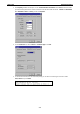
IKS-6726 Featured Functions LLDP Web Interface From the switch’s web interface, users have the option of either enabling or disabling LLDP, as well as setting the LLDP transmit interval (as shown in the figure below). In addition, users are able to view each switch’s neighbor-list, which is reported by its network neighbors.
IKS-6726 Featured Functions Multi-cast packets (in green color), and Broad-cast packets (in blue color). The graph is updated every few seconds, allowing the user to analyze data transmission activity in real-time. Monitor by Port Access the Monitor by Port function by selecting ALL 10/100M or 1G Ports or Port i, in which i = 1, 2, …, G2, from the left pull-down list.
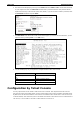
IKS-6726 Featured Functions Using the MAC Address Table This section explains the information provided by IKS-6726’s MAC address table. The MAC Address table can be configured to display the following IKS-6726 MAC address groups.
IKS-6726 NOTE Featured Functions The following events will be record into IKS-6726’s Event Log Table. • Cold start • Warm start • Configuration change activated • Power 1/2 transition (Off ( On), Power 1/2 transition (On ( Off) • Authentication fail • Topology changed • Master setting is mismatched • Port traffic overload • dot1x Auth Fail • Port link off / on Using Syslog This function provides the event logs for the syslog server.
IKS-6726 NOTE Featured Functions The following events will be recorded into the IKS-6726’s Event Log table, and will then be sent to the specified Syslog Server: • Cold start • Warm start • Configuration change activated • Power 1/2 transition (Off ( On), Power 1/2 transition (On ( Off) • Authentication fail • Topology changed • Master setting is mismatched • Port traffic overload • dot1x Auth Fail • Port link off / on Using HTTPS/SSL To secure your HTTP access, the IKS-6726 supports
A A. MIB Groups The IKS-6726 comes with built-in SNMP (Simple Network Management Protocol) agent software that supports cold/warm start trap, line up/down trap, and RFC 1213 MIB-II. The standard MIB groups that the IKS-6726 supports are as follows: MIB II.1—System Group sysORTable MIB II.2—Interfaces Group ifTable MIB II.4 – IP Group ipAddrTable ipNetToMediaTable IpGroup IpBasicStatsGroup IpStatsGroup MIB II.5—ICMP Group IcmpGroup IcmpInputStatus IcmpOutputStats MIB II.
IKS-6726 MIB Groups dot1dTpPortTable dot1dTpHCPortTable dot1dTpPortOverflowTable pBridgeMIB dot1dExtBase dot1dPriority dot1dGarp qBridgeMIB dot1qBase dot1qTp dot1qFdbTable dot1qTpPortTable dot1qTpGroupTable dot1qForwardUnregisteredTable dot1qStatic dot1qStaticUnicastTable dot1qStaticMulticastTable dot1qVlan dot1qVlanCurrentTable dot1qVlanStaticTable dot1qPortVlanTable The IKS-6726 also provides a private MIB file, located in the file Moxa-IKS-6726-MIB.my on the IKS-6726 utility CD-ROM.
B B. Modbus/TCP Map IKS-6726 Modbus Information v1.
IKS-6726 0x0058 Modbus/TCP Map 1 word Power 1 0x0000:Off 0x0001:On 0x0059 1 word Power 2 0x0000:Off 0x0001:On 0x005A 1 word Fault LED Status 0x0000:No 0x0001:Yes 0x0080 1 word DI1 0x0000:Off 0x0001:On 0x0082 1 word DO1 0x0000:Off 0x0001:On Port Information 0x1000 to 0x1019 1 word Port 1 to 26 Status 0x0000:Link down 0x0001:Link up 0x0002:Disable 0xFFFF:No port 0x1100 to 0x1119 1 word Port 1 to 26 Speed 0x0000:10M-Half 0x0001:10M-Full 0x0002:100M-Half 0x0003:100M-Full 0x0004:1G-Half 0x000
IKS-6726 0x2100 to 0x2133 Modbus/TCP Map 2 words Port 1 to 26 Rx Packets Ex: port 1 Rx Packets = 0x44332211 Word 0 = 4433 Word 1 = 2211 0x2200 to 0x2233 2 words port 1 to 26 Tx Error Packets Ex: port 1 Tx Error Packets = 0x44332211 Word 0 = 4433 Word 1 = 2211 0x2300 to 0x2333 2 words port 1 to 26 Rx Error Packets Ex: port 1 Rx Error Packets = 0x44332211 Word 0 = 4433 Word 1 = 2211 Redundancy Information 0x3000 1 word Redundancy Protocol 0x0000:None 0x0001:RSTP 0x0002:Turbo Ring 0x0003:Turbo Ring
IKS-6726 0x3304 Modbus/TCP Map 1 word TR Coupling Port status 0x0000:Port Disabled 0x0001:Not Coupling Port 0x0002:Link Down 0x0003:Blocked 0x0005:Forwarding 0xFFFF:Turbo Ring Not Enable 0x3305 1 word TR Coupling Control Port status 0x0000:Port Disabled 0x0001:Not Coupling Port 0x0002:Link Down 0x0003:Blocked 0x0005:Forwarding 0x0006:Inactive 0x0007:Active 0xFFFF:Turbo Ring Not Enable 0x3500 1 word TR2 Coupling Mode 0x0000:None 0x0001:Dual Homing 0x0002:Coupling Backup 0x0003:Coupling Primary 0xFFFF
IKS-6726 0x3602 Modbus/TCP Map 1 word TR2 Ring 1 1st Port status 0x0000:Port Disabled 0x0001:Not Redundant 0x0002:Link Down 0x0003:Blocked 0x0004:Learning 0x0005:Forwarding 0xFFFF:Turbo Ring V2 Ring 1 Not Enable 0x3603 1 word TR2 Ring 1 2nd Port status 0x0000:Port Disabled 0x0001:Not Redundant 0x0002:Link Down 0x0003:Blocked 0x0004:Learning 0x0005:Forwarding 0xFFFF:Turbo Ring V2 Ring 1 Not Enable 0x3680 1 word TR2 Ring 2 status 0x0000:Healthy 0x0001:Break 0xFFFF:Turbo Ring V2 Ring 2 Not Enable 0x36
IKS-6726 0x3702 Modbus/TCP Map 1 word Turbo Chain 2nd Port Status 0x0000:Link Down 0x0001:Blocking 0x0002:Blocked 0x0003:Forwarding 0xFFFF:Turbo Chain Not Enable Memory mapping from address 0x0000 to 0x3FFF.