
Installation guide


8
Wall Mounting (optional)
For some applications, you will find it convenient to mount EDS-P308 Series
on the wall, as illustrated below.
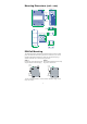
STEP 1:
Remove the aluminum
DIN-Rail attachment plate
from the EDS-P308’s rear
panel, and then attach the
wall mount plates, as shown
in the diagram below.
⇒
top
plate
bottom
plate
STEP 2:
Mounting the EDS-P308 on the wall requires 4 screws.
Use the switch, with wall mount plates attached, as a
guide to mark the correct locations of the 4 screws. The
heads of the screws should be less than 6.0 mm in
diameter, and the shafts should be less than 3.5 mm in
diameter, as shown in the figure at the right.
6.0 mm
3.5 mm
NOTE
Before tightening the screws into the wall, make sure the screw
head and shank size are suitable by inserting the screw into one of
the keyhole-shaped apertures of the wall mounting plates.
Do not screw the screws in all the way—leave about 2 mm to allow room for
sliding the wall mount panel between the wall and the screws.
STEP 3:
Once the screws are fixed in the wall, insert
the four screw heads through the large parts
of the keyhole-shaped apertures, and then
slide the EDS-P308 downwards, as indicated.
Tighten the four screws for added stability.
⇒
Grounding the EDS-P308 Series
Grounding and wire routing help limit the effects of noise due to
electromagnetic interference (EMI). Run the ground connection from the
ground screw to the grounding surface prior to connecting devices.
ATTENTION
This product is intended to be mounted to a well-grounded
mounting surface, such as a metal panel.