
Installation guide


10
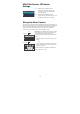
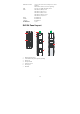
EDS-P308 Series’s DIP Switch
Settings
12345678
ON DIP
ON: Enables the corresponding PORT
Alarm. If the port’s link fails, the relay
will form an open circuit and the fault
LED will light up.
Off: Disables the corresponding PORT
Alarm. The relay will form a closed circuit
and the Fault LED will never light up.
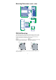
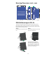
Wiring the Alarm Contact
The alarm contact consists of the two middle contacts of the terminal block on
EDS’s top panel. Refer to below for detailed instructions on how to connect the
wires to the terminal block connector, and how to attach the terminal block
connector to the terminal block receptor. In this section, we explain the
meaning of the two contacts used to connect the alarm contact.
FAULT
FAULT
Top View
Front View
FAULT: The two middle contacts of the 6-contact
terminal block connector are used to detect both
power faults and port faults. The two wires
attached to the Fault contacts form an open circuit
when:
1. EDS has lost power from one of the DC power
inputs.
OR
2. One of the ports for which the corresponding
PORT ALARM DIP Switch is set to ON is not
properly connected.
If neither of these two conditions is satisfied, the
Fault circuit will be closed.