
Installation guide


9
EDS-P308 Series’s Redundant Power
Inputs
Both power inputs can be connected simultaneously to live DC power sources.
If one power source fails, the other live source acts as a backup, and
automatically supplies all of EDS-P308 Series’s power needs.
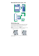
Wiring the Redundant Power Inputs
The top two contacts and the bottom two contacts of the 6-contact terminal
block connector on EDS’s top panel are used for EDS’s two DC inputs. Top
and front views of one of the terminal block connectors are shown here.
Top View
Front View
STEP 1:
Insert the negative/positive DC wires into the
V-/V+ terminals.
STEP 2:
To keep the DC wires from pulling loose, use
a small flat-blade screwdriver to tighten the
wire-clamp screws on the front of the
terminal block connector.
STEP 3:
Insert the plastic terminal block connector
prongs into the terminal block receptor,
which is located on EDS’s top panel.
ATTENTION
Before connecting EDS to the DC power inputs, make sure the
DC power source voltage is stable.
EDS-P308 Series’s Alarm Contact
The EDS-P308 Series has one alarm contact located on its top panel. For
detailed instructions on how to connect the alarm contact power wires to the
two middle contacts of the 6-contact terminal block connector, see the Wiring
the Alarm Contact section on page 10. A typical scenario would be to connect
the Fault circuit to a warning light located in the control room. The light can be
set up to switch on when a fault is detected.
The alarm contact has two terminals that form a Fault circuit for connecting to
an alarm system. The two wires attached to the Fault contacts form an open
circuit when (1) EDS has lost power from one of the DC power inputs, or (2)
one of the ports for which the corresponding PORT ALARM DIP Switch is set
to ON is not properly connected.
If neither of these two conditions occurs, the Fault circuit will be closed.