
Installation Guide
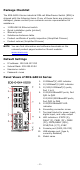
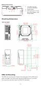
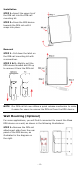
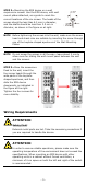
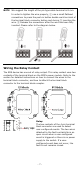
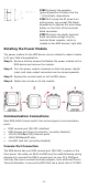
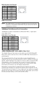
Table Of Contents
- EDS-G4014 Series Quick Installation Guide
- Package Checklist
- Default Settings
- Panel Views of EDS-G4014 Series
- Mounting Dimensions
- DIN-rail Mounting
- Wall Mounting (Optional)
- Wiring Requirements
- Grounding the Moxa EDS Series
- Suggested Wire Type for Wiring Relay Contact (RELAY), Digital Input (DI), and Power Inputs (P1/P2)
- Wiring the Relay Contact
- Wiring the Redundant Power Inputs
- Wiring the Digital Inputs
- Rotating the Power Module
- Communication Connections
- Reset Button
- Turbo Ring DIP Switch Settings
- LED Indicators
- Specifications

- 7 -
NOTE
We suggest the length of the pin type cable terminal is 8 mm.
In order to tighten the wire properly,
① use a small flathead
screwdriver to press the push
-
in button beside each terminal of
the terminal block connector before and during
②
inserting the
wire.
③ Release the screwdriver after the wire has been fully
inserted. Please refer to the diagram below.
Wiring the Relay Contact
The EDS device has one set of relay output. This relay contact uses two
contacts of the terminal block on the EDS’s power module. Refer to the
section for detailed instructions on how to connect the wires to the
terminal block connector, and how to attach the terminal block
connector to the terminal block receptor.
Relay:
The two contacts of
the 4-pin terminal
block connector are used to detect
user
-configured events. The two wires
attached to the
fault contacts form an
open circui
t when a user-configured
event is triggered or
there is no power
supply to the switch
. If a user-
configured event does not oc
cur, the
fault circuit remains closed.