
Installation Guide
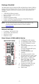
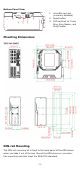
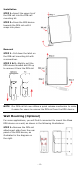
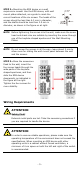
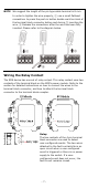
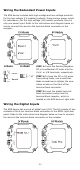
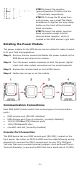
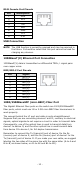
Table Of Contents
- EDS-G4014 Series Quick Installation Guide
- Package Checklist
- Default Settings
- Panel Views of EDS-G4014 Series
- Mounting Dimensions
- DIN-rail Mounting
- Wall Mounting (Optional)
- Wiring Requirements
- Grounding the Moxa EDS Series
- Suggested Wire Type for Wiring Relay Contact (RELAY), Digital Input (DI), and Power Inputs (P1/P2)
- Wiring the Relay Contact
- Wiring the Redundant Power Inputs
- Wiring the Digital Inputs
- Rotating the Power Module
- Communication Connections
- Reset Button
- Turbo Ring DIP Switch Settings
- LED Indicators
- Specifications

- 5 -
STEP 2—Mounting the EDS device on a wall
requires
six screws. Use the EDS device, with wall
mount plates attached, as a guide to mark the
correct locations of the
six screws. T
he heads of the
screws should be less than 6.0 mm in diameter,
and the shafts should be less than 3.5
mm in
diameter, as shown in the figure on at right.
NOTE
Before tightening the screws into the wall, make sure the screw
head and shank size are suitable by inserting the screw through
one of the keyhole
-shaped apertures of the Wall Mounting
Plates.
NOTE
Do not screw the screws in all the way—leave about 2 mm to
allow room for sliding the wall mount panel between the wall
and the screws.
STEP 3—Once the screws are
fixed
to the wall, insert the
four screw heads through the
wide parts of the keyhole
-
shaped apertures, and then
slide
the EDS device
downwards, as indicated
in
the figure
at the right.
Tighten the four screws for
more
stability.
Wiring Requirements
ATTENTION
Safety First!
External metal parts are hot. Take
the necessary precautions if
you are required to handle the device.
ATTENTION
In order to ensure reliable operations, please make sure the
operating temperature of the environment does not exceed the
specifications. When mounting an EDS device with other
operating units in a cabinet without forced ventilation, a
minimum of
4 cm spac
e on both the left and right of the switch
is recommended.