
Installation Guide
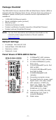
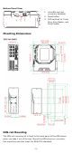
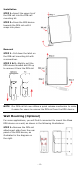
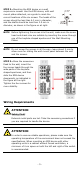
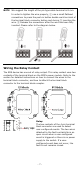
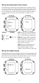
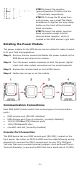
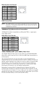
Table Of Contents
- EDS-G4014 Series Quick Installation Guide
- Package Checklist
- Default Settings
- Panel Views of EDS-G4014 Series
- Mounting Dimensions
- DIN-rail Mounting
- Wall Mounting (Optional)
- Wiring Requirements
- Grounding the Moxa EDS Series
- Suggested Wire Type for Wiring Relay Contact (RELAY), Digital Input (DI), and Power Inputs (P1/P2)
- Wiring the Relay Contact
- Wiring the Redundant Power Inputs
- Wiring the Digital Inputs
- Rotating the Power Module
- Communication Connections
- Reset Button
- Turbo Ring DIP Switch Settings
- LED Indicators
- Specifications

- 4 -
Installation
STEP 1—Insert the upper lip of
the DIN r
ail into the DIN-rail
mounting kit.
STEP 2
—Press the EDS device
towards the
DIN rail until it
snaps into place.
Removal
STEP 1
—
Pull down the latch on
the
DIN-rail mounting kit with
a screwdriver.
STEP 2
& 3—Slightly pull the
EDS device forward and lift up
to remove it from the DIN rail.
NOTE
Our
DIN rail kit now u
tilizes a quick release mechanism to make
it easier for users to remove the DIN rail from the EDS device.
Wall Mounting (Optional)
For some applications, you will find it convenient to mount the Moxa
EDS device on a wall, as shown in the following illustrations:
STEP 1—Remove the DIN-rail
attachment pl
ate from the rear
panel of the EDS device,
as
illustrated
in the diagram on
the
right.