
Installation Guide
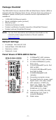
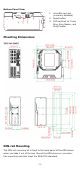
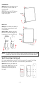
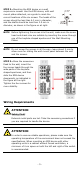
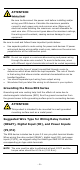
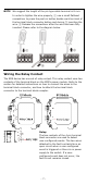
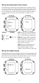
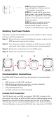
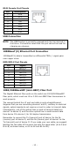
Table Of Contents
- EDS-G4014 Series Quick Installation Guide
- Package Checklist
- Default Settings
- Panel Views of EDS-G4014 Series
- Mounting Dimensions
- DIN-rail Mounting
- Wall Mounting (Optional)
- Wiring Requirements
- Grounding the Moxa EDS Series
- Suggested Wire Type for Wiring Relay Contact (RELAY), Digital Input (DI), and Power Inputs (P1/P2)
- Wiring the Relay Contact
- Wiring the Redundant Power Inputs
- Wiring the Digital Inputs
- Rotating the Power Module
- Communication Connections
- Reset Button
- Turbo Ring DIP Switch Settings
- LED Indicators
- Specifications

- 2 -
Package Checklist
The EDS-G4014 Series industrial DIN-rail EtherDevice Switch (EDS) is
shipped with the following items. If any of these items are missing or
damaged, please contact your customer service representative for
assistance.
• 1 EDS-G4014 Ethernet switch
• Quick installation guide (printed)
• Warranty card
• Substance disclosure table
• Product certificate of quality inspection (Simplified Chinese)
• Product notices (Simplified Chinese)
NOTE
You can find information and software downloads on the
relevant product pages located on Moxa’s website:
www.moxa.com
Default Settings
• IP address: 192.168.127.253
• Subnet Mask: 255.255.255.0
• Username: admin
• Password: moxa
Panel Views of EDS-G4014 Series
1. 1000BaseT(X) LED indicator
2. 10/100BaseT(X) LED indicator
3. 10/100/1000BaseT(X) ports,
Port 1 to 8
4. 1000/2500BaseSFP ports, Port
QG1 to QG2
100/1000/2500BaseSFP ports,
Port QG3 to QG6
5. 1000/2500BaseSFP LED
indicator
6. Grounding connector screw
7.
Terminal blocks for power input,
digital input, and relay output
8. LED indicators: STATE (S),
FAULT (F), PWR1 (P1), PWR2
(P2), MSTR/HEAD (M/H),
CPLR/TAIL (C/T), SYNC
9. Console port (RJ45, RS-232)
10.
USB storage port (type A,
currently disabled)
11. Model name