
Installation Guide
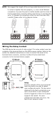
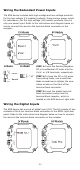
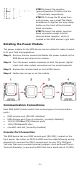
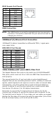


Table Of Contents
- EDS-G4014 Series Quick Installation Guide
- Package Checklist
- Default Settings
- Panel Views of EDS-G4014 Series
- Mounting Dimensions
- DIN-rail Mounting
- Wall Mounting (Optional)
- Wiring Requirements
- Grounding the Moxa EDS Series
- Suggested Wire Type for Wiring Relay Contact (RELAY), Digital Input (DI), and Power Inputs (P1/P2)
- Wiring the Relay Contact
- Wiring the Redundant Power Inputs
- Wiring the Digital Inputs
- Rotating the Power Module
- Communication Connections
- Reset Button
- Turbo Ring DIP Switch Settings
- LED Indicators
- Specifications

- 13 -
LED
Color
State
Description
Red On
The system has initially failed
the boot-up process
• System Info. Read Fail or
EEPROM information error
FAULT Red
On
1.
The relay contact has been
triggered
2. The ingress rate limit has
been exceeded and the port
has entered shut down
mode
3. Invalid Ring port connection
Off
When the system boots up and
runs correctly or a user-
configured event is not
triggered.
P1 Amber
On
Power is being supplied to power
input PWR.
Off
Power is not being supplied to
power input PWR.
P2 Amber
On
Power is being supplied to power
input PWR.
Off
Power is not being supplied to
power input PWR.
MSTR/
HEAD
(M/H)
Green
On
When the switch is
Master/Head/Root of Turbo
Ring/Turbo Chain/Fast RSTP.
Blinking
(4 times/sec)
1. The switch has become the
Master of Turbo Ring after
Turbo Ring has gone down
2. The switch is set as Head of
Turbo Chain and Turbo
Chain has gone down
3. The switch is set as the
Turbo Ring’s Member and
the corresponding Ring port
is down
4. The switch is set as the
Turbo Chain’s Member/ Tail
and the corresponding
Head-end Chain port is
down.
Off
When the switch is not the
Master/Head/Root of this Turbo
Ring/ Turbo Chain/Fast RSTP.
CPLR/
TAIL
Green On
1. The switch’s ring coupling or
dual homing function is
enabled.
2. The switch is set as the Tail
of Turbo Chain.