
Installation Guide
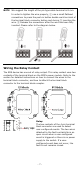
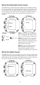
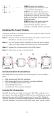
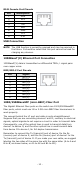


Table Of Contents
- EDS-G4014 Series Quick Installation Guide
- Package Checklist
- Default Settings
- Panel Views of EDS-G4014 Series
- Mounting Dimensions
- DIN-rail Mounting
- Wall Mounting (Optional)
- Wiring Requirements
- Grounding the Moxa EDS Series
- Suggested Wire Type for Wiring Relay Contact (RELAY), Digital Input (DI), and Power Inputs (P1/P2)
- Wiring the Relay Contact
- Wiring the Redundant Power Inputs
- Wiring the Digital Inputs
- Rotating the Power Module
- Communication Connections
- Reset Button
- Turbo Ring DIP Switch Settings
- LED Indicators
- Specifications

- 12 -
Turbo Ring DIP Switch Settings
The default
setting for each DIP Switch is OFF. The
following table explains the effect of setting the DIP
Switch to the ON position
.
Remove the rubber cover on the bottom panel of
the device
to expose the DIP switches.
DIP Switch Settings
DIP 1
DIP 2
DIP 3
DIP 4
DIP 5
Reserved
for future
use
ON:
Enables the
default “Ring
Coupling
(backup)” port
when DIP switch 4
is already enabled.
ON:
Enables
this EDS as
the Ring
Master.
ON:
Enables the
default
“Ring
Coupling”
port.
ON:
Activates
DIP switch 2,
3, and 4 to
configure
Turbo Ring V2
settings.
OFF:
Enables the
default Ring
Coupling
(primary) port
when DIP switch 4
is already enabled.
OFF:
This
EDS will not
be the Ring
Master.
OFF:
This
EDS will not
be the Ring
Coupler.
OFF:
DIP
switch 2, 3,
and 4 will be
disabled.
NOTE
You must enable the
Turbo Ring (DIP switch 5) first before
using the DIP switch to activate the Master and Coupler
functions.
NOTE
If you do not enable any of t
he EDS switches to be the Ring
Master, the Turbo Ring protocol will
automatically choose the
EDS switch
with the smallest MAC address range to b
e the Ring
Master. If you accidentally enable more
than one switch to be
the Ring Master, these switches will auto
-negotiate to
determine which one will be the Ring Master.
LED Indicators
The front panel of the Moxa EDS-G4014 Series contains several LED
indicators. The function of each LED is described in the following table:
Device LED Indicators
LED
Color
State
Description
STATE Green
On
When system has passed power-
on self-test (POST) and is ready
to run.
Blinking
(1 time/sec)
Press the reset button for five
seconds to reset to factory
default settings
Blinking
(4 times/sec)
When pressing the reset button
depress for 5 seconds to reset to
factory default.
Off
N/A