EDS-G4014 Series Quick Installation Guide Moxa EtherDevice™ Switch Version 1.0, March 2022 Technical Support Contact Information www.moxa.com/support 2022 Moxa Inc. All rights reserved.
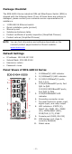
Package Checklist The EDS-G4014 Series industrial DIN-rail EtherDevice Switch (EDS) is shipped with the following items. If any of these items are missing or damaged, please contact your customer service representative for assistance.
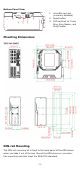
Bottom Panel View 1. 2. 3. microSD card slot (currently disabled) Reset button DIP switches for Turbo Ring, Ring Master, and Ring Coupler Mounting Dimensions DIN-rail Mounting The DIN-rail mounting kit is fixed to the back panel of the EDS device when you take it out of the box. Mount the EDS device on corrosionfree mounting rails that meet the EN 60715 standard.
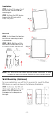
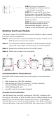
Installation STEP 1—Insert the upper lip of the DIN rail into the DIN-rail mounting kit. STEP 2—Press the EDS device towards the DIN rail until it snaps into place. Removal STEP 1—Pull down the latch on the DIN-rail mounting kit with a screwdriver. STEP 2 & 3—Slightly pull the EDS device forward and lift up to remove it from the DIN rail. NOTE Our DIN rail kit now utilizes a quick release mechanism to make it easier for users to remove the DIN rail from the EDS device.
STEP 2—Mounting the EDS device on a wall requires six screws. Use the EDS device, with wall mount plates attached, as a guide to mark the correct locations of the six screws. The heads of the screws should be less than 6.0 mm in diameter, and the shafts should be less than 3.5 mm in diameter, as shown in the figure on at right.
ATTENTION Safety First! Be sure to disconnect the power cord before installing and/or wiring your EDS device. Calculate the maximum possible current in each power wire and common wire. Observe all electrical codes dictating the maximum current allowable for each wire size. If the current goes above the maximum ratings, the wiring could overheat, causing serious damage to your equipment. Be sure to read and follow these important points below: • Use separate paths to route wiring for power and devices.
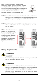
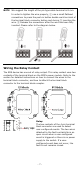
NOTE We suggest the length of the pin type cable terminal is 8 mm. In order to tighten the wire properly, ① use a small flathead screwdriver to press the push-in button beside each terminal of the terminal block connector before and during ② inserting the wire. ③ Release the screwdriver after the wire has been fully inserted. Please refer to the diagram below. Wiring the Relay Contact The EDS device has one set of relay output.
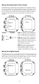
Wiring the Redundant Power Inputs The EDS device includes both high-voltage and low-voltage products. For the low-voltage (LV models) products, there are two power inputs for redundancy; for the high-voltage (HV models) products, there is only one power input. Refer to the instructions and diagram below on how to connect the wires to the terminal block connector on the receptor. STEP 1: Insert the Positive/Negative DC or Line/Neutral AC wires into the V+/V- or L/N terminals, respectively.
STEP 1: Insert the negative (ground)/positive DI wires into the ┴/I terminals, respectively. STEP 2: To keep the DI wires from pulling loose, use a small flat-blade screwdriver to tighten the wire-clamp button on the front of the terminal block connector. STEP 3: Insert the plastic terminal block connector prongs into the terminal block receptor, which is located on the EDS devices’ right side.
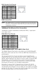
RJ45 Console Port Pinouts Pin 1 2 3 4 5 6 7 8 Description DSR RTS – TxD RxD GND CTS DTR USB Connection NOTE The USB function is currently reserved and may be required in the future. It should be noted that this port cannot be used for charging any devices. 1000BaseT(X) Ethernet Port Connection 1000BaseT(X) data is transmitted on differential TRD+/- signal pairs over copper wires.
LC-Port Pinouts LC-Port to LC-Port Cable Wiring ATTENTION This is a Class 1 Laser/LED product. To avoid causing serious damage to your eyes, do not stare directly into the Laser Beam. Reset Button There are two functions available on the Reset Button. One is to reset the Ethernet switch to factory default settings by pressing and holding the Reset button for 5 seconds. Use a pointed object, such as a straightened paper clip or toothpick, to depress the Reset button.
Turbo Ring DIP Switch Settings The default setting for each DIP Switch is OFF. The following table explains the effect of setting the DIP Switch to the ON position. Remove the rubber cover on the bottom panel of the device to expose the DIP switches. DIP Switch Settings DIP 1 DIP 2 ON: Enables the default “Ring Coupling (backup)” port when DIP switch 4 Reserved is already enabled. for future OFF: Enables the use default Ring Coupling (primary) port when DIP switch 4 is already enabled.
LED Color Red FAULT Red P1 Amber P2 Amber MSTR/ HEAD (M/H) Green CPLR/ TAIL Green State Description The system has initially failed the boot-up process On • System Info. Read Fail or EEPROM information error 1. The relay contact has been triggered 2. The ingress rate limit has been exceeded and the port On has entered shut down mode 3. Invalid Ring port connection When the system boots up and runs correctly or a userOff configured event is not triggered.
LED System LED (Except PWR) System LED (Except PWR) Color State Description 1. The switch is set as the Tail of Turbo Chain and the Chain has gone down. Blinking 2. The switch is set as the (4 times/sec) Turbo Chain’s Member/ Head and the corresponding Tail-end Chain port is down. When the switch disables the Off coupling or tail role of Turbo Chain. Green + The switch is being Blinking discovered/located by the Amber + (2 times/sec) locator function.
LED Indicators Alarm Contact Digital Input STATE (S), FAULT (F), PWR1 (P1), PWR2 (P2), MSTR/HEAD (M/H), CPLR/TAIL (C/T), SYNC 1 normally open electromagnetic relay output with current carrying capacity of 1 A @ 24 VDC 1 isolated digital input: +13 to +30V for state “1” -30 to +3V for state “0” Max. input current: 8 mA Power Pre-installed Power -LV/-LV-T models: PWR-100-LV Module -HV/-HV-T models: PWR-105-HV-I Note The EDS-G4014 Series supports modular power supplies.
Altitude Up to 2000 m Note: Please contact Moxa if you require products guaranteed to function properly at higher altitude.