
Installation Guide
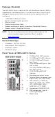
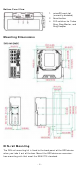
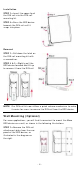
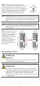
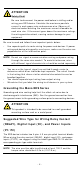
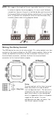
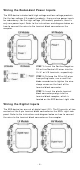
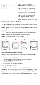
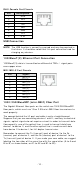
Table Of Contents
- EDS-G4014 Series Quick Installation Guide
- Package Checklist
- Default Settings
- Panel Views of EDS-G4014 Series
- Mounting Dimensions
- DIN-rail Mounting
- Wall Mounting (Optional)
- Wiring Requirements
- Grounding the Moxa EDS Series
- Suggested Wire Type for Wiring Relay Contact (RELAY), Digital Input (DI), and Power Inputs (P1/P2)
- Wiring the Relay Contact
- Wiring the Redundant Power Inputs
- Wiring the Digital Inputs
- Rotating the Power Module
- Communication Connections
- Reset Button
- Turbo Ring DIP Switch Settings
- LED Indicators
- Specifications

- 9 -
STEP 1 : I nsert t he negat ive
(ground) / posit ive DI w ires int o t he
┴
/ I t erm inals, respectively.
STEP 2 :
To keep the DI wir es from
pulling loose, use a sm all flat
-blade
scr ew dr iver t o t ight en the wir e
-clam p
but t on
on t he front of t he ter m inal
block connect or .
STEP 3 :
I nser t t he plast ic ter m inal
block connect or pron gs int o t he
ter m inal block recept or, w hich is
locat ed on t he EDS devices’ r ight side.
Rot a t in g t he Pow er Mod u le
The power m odule for t he EDS device can be rot at ed t o m ake it easier
to fit y our field site application.
St ep 1 :
Rem ov e
the t w o screws t hat fast en t he pow er m odule to t he
EDS device
and r em ove t he m odule.
St ep 2 :
Turn the power m odule clockw ise so that t he power , digit al
input
, and r elay out put connect ors can be m oved u pw ar ds.
St ep 3 :
Replace t he m odule back
on t o t he EDS device.
St ep 4 :
Fast en t w o screws on
t o t he m odule.
Com m unica t ion Conne ct ions
Each EDS- G4014 Series sw it ch has various t ypes of com m unicat ion
port s:
• RJ45 console port ( RS- 232 int erface)
• USB st orage port (t ype A connect or, current ly disabled)
• 10/ 100/ 1000BaseT(X) Ether net port s
• 1000/ 2500BaseSFP slot s
• m icroSD car d slot ( curr ent ly disabled)
Con sole Port Con n e ct ion
The EDS dev ice has one RJ45 console por t ( RS-23 2), locat ed on t he
front panel. Use eit her an RJ45- t o- DB9 ( see t he cable follow ing wiring
diagr am s) t o connect t he EDS’s console por t t o your PC’s COM port .
You m ay t hen use a console ter m inal program , such as Moxa PCom m
Ter m inal Em ulat or , t o access t he EDS that has a baud rat e of 1152 00.