
Installation Guide
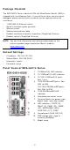
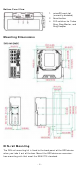
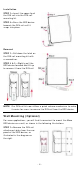
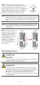
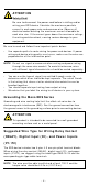
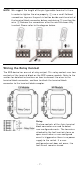
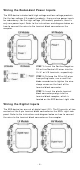
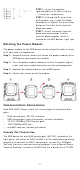
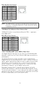
Table Of Contents
- EDS-G4014 Series Quick Installation Guide
- Package Checklist
- Default Settings
- Panel Views of EDS-G4014 Series
- Mounting Dimensions
- DIN-rail Mounting
- Wall Mounting (Optional)
- Wiring Requirements
- Grounding the Moxa EDS Series
- Suggested Wire Type for Wiring Relay Contact (RELAY), Digital Input (DI), and Power Inputs (P1/P2)
- Wiring the Relay Contact
- Wiring the Redundant Power Inputs
- Wiring the Digital Inputs
- Rotating the Power Module
- Communication Connections
- Reset Button
- Turbo Ring DIP Switch Settings
- LED Indicators
- Specifications

- 7 -
N OTE
We suggest t he length of t he pin t ype cable t er m inal is 8 m m .
I n order t o tight en t he wire proper ly,
① use a sm all flathead
screwdriver t o press t he push
-
in but ton beside each t er m inal of
the t erm inal block connect or befor e and durin g
②
inser ting t he
wire.
③ Release t he screwdriver after the wir e has been fully
insert ed. Please refer t o t he diagram below .
W irin g t he Re la y Cont a ct
The EDS device has one set of relay out put . This relay cont act uses t wo
cont act s of t he t erm inal block on the EDS’s power m odule. Refer t o t he
sect ion for det ailed inst ruct ions on how t o connect t he wires t o t he
term inal block connect or , and how to att ach t he term inal block
connect or t o t he t erm inal block r ecept or.
Re la y:
The t wo cont act s of
the 4 -pin t erm inal
block connector are used to det ect
user
-configured event s. The t wo w ires
at tached t o the
fault cont act s for m an
open cir cu i
t w hen a user -configured
event is triggered or
there is no pow er
supply t o t he sw it ch
. I f a u ser-
configured event does not oc
cur, t he
fault cir cu it rem ains closed.