
Installation Guide
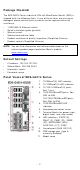
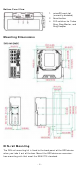
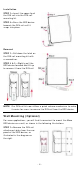
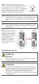
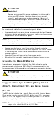
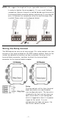
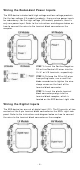
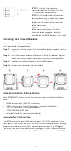
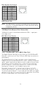
Table Of Contents
- EDS-G4014 Series Quick Installation Guide
- Package Checklist
- Default Settings
- Panel Views of EDS-G4014 Series
- Mounting Dimensions
- DIN-rail Mounting
- Wall Mounting (Optional)
- Wiring Requirements
- Grounding the Moxa EDS Series
- Suggested Wire Type for Wiring Relay Contact (RELAY), Digital Input (DI), and Power Inputs (P1/P2)
- Wiring the Relay Contact
- Wiring the Redundant Power Inputs
- Wiring the Digital Inputs
- Rotating the Power Module
- Communication Connections
- Reset Button
- Turbo Ring DIP Switch Settings
- LED Indicators
- Specifications

- 6 -
ATTEN TI ON
Sa fe t y Fir st !
Be sure t o disconnect the power cord before in stalling and/ or
wiring your EDS device. Calculat e t he m axim u m possible
current in each
pow er w ire and com m on w ire. Obser ve all
elect rical codes dict ating the m axim um current allow able for
each wir e size. I f t he current goes above t he m axim um rat ings,
the w iring could overheat , causing ser ious dam age to your
equipm ent .
Be sur e to read and follow t hese im por t ant point s below :
• Use separat e pat hs t o rout e wir ing for pow er and devices. I f pow er
wiring and device w iring pat hs m ust cr oss, m ake sure t he wires are
per pendicular at the intersect ion point.
N OTE
Do not run signal or com m unications w iri
ng and pow er w iring
thr ough t he sam e w ire conduit . To avoid inter ference, w ires
with different signal char act erist ics should be rout ed separ ately.
• You can use t he t ype of signal tr ansm it t ed t hrough a w ire t o
det erm ine which wires should be k ept separate. The rule of t hum b
is t hat wir ing t hat shares sim ilar elect rical charact erist ics can be
bundled t oget her .
• You should separat e input w iring from out put wiring.
• We advise t hat you label t he w iring to all devices in y our syst em .
Gr ounding t h e M ox a ED S Series
Grounding and wire rout ing help lim it t he effect s of noise due t o
electr om agnet ic int erference (EMI ) . Run the ground connect ion from
the ground screw t o t he grounding surface pr ior t o connecting devices.
ATTEN TI ON
T
his pr oduct is int ended t o be m ount ed t o a well- gr ounded
m ounting surface such as a met al panel.
Sug ge st e d W ir e Type for W iring Rela y Con t a ct
( RELAY) , Digit a l I nput ( DI ) , a nd Pow e r I nput s
( P1 / P2 )
The EDS device includes t wo 4-pins 3.5 m m pin-pit ch t erm inal block s.
When w iring t he r elay cont act ( RELAY), digit al input (DI ) , and pow er
inputs ( P1/ P2), we suggest u sing t he cable t ype AWG 18- 24 and t he
cor responding pin t ype cable term inals.
N OTE
The wir e m ust be
able t o wit hst and at least 105 ° C an d t he
torque value should be 4.5 lb- in ( 0.51 N- m ) .