
Installation Guide

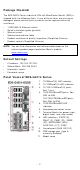
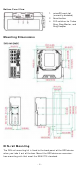
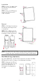
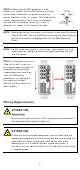
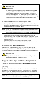
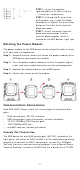
Table Of Contents
- EDS-G4014 Series Quick Installation Guide
- Package Checklist
- Default Settings
- Panel Views of EDS-G4014 Series
- Mounting Dimensions
- DIN-rail Mounting
- Wall Mounting (Optional)
- Wiring Requirements
- Grounding the Moxa EDS Series
- Suggested Wire Type for Wiring Relay Contact (RELAY), Digital Input (DI), and Power Inputs (P1/P2)
- Wiring the Relay Contact
- Wiring the Redundant Power Inputs
- Wiring the Digital Inputs
- Rotating the Power Module
- Communication Connections
- Reset Button
- Turbo Ring DIP Switch Settings
- LED Indicators
- Specifications

- 5 -
STEP 2 —Mount ing t he EDS device on a w all
requires
six screws. Use t he EDS device, with w all
m ount plat es at t ached, as a guide t o m ark t he
cor rect locat ions of t he
six scr ew s. T
he heads of t he
screws sh ould be less t han 6.0 m m in diam et er,
and t he shaft s should be less t han 3.5
m m in
diam et er, as sh own in t he figure on at r ight .
N OTE
Befor e t ightening t he screws int o t he wall, m ake sure t he scr ew
head and shank size are suit able by insert ing t he screw t hrough
one of the keyhole
-shaped apert ures of t he Wall Mount ing
Plat es.
N OTE
Do not scr ew t he screw s in all t he w ay—leave about 2 m m t o
allow room for sliding t he w all m ount panel bet ween t he w all
and t he scr ew s.
STEP 3 —Once t he screws ar e
fixed
to the w all, insert t he
four scr ew heads t hrough the
wide part s of the keyhole
-
shaped aper tures, and then
slide
the EDS device
dow nwards, as indicat ed
in
the figure
at the right .
Tighten t he four screw s for
m or e
st abilit y.
W irin g Re quir em e nt s
ATTEN TI ON
Sa fe t y Fir st !
Ext ernal m etal part s are hot . Take
the necessar y pr ecaut ion s if
you are r equired t o handle t he device.
ATTEN TI ON
I n order t o ensure reliable oper at ions, please m ake sure the
operat ing t em perat ur e of t he en vironm ent does not exceed t he
specificat ions. When m ount ing an EDS device wit h ot her
operat ing unit s in a cabinet w it hout forced vent ilation, a
m in im u m of
4 cm spac
e on bot h t he left and right of t he sw it ch
is recom m ended.