
Installation Guide
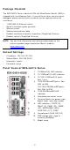
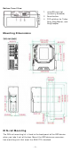
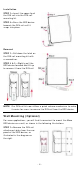
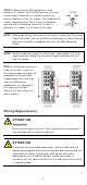
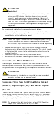
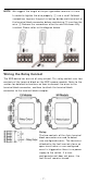
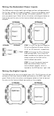
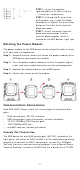
Table Of Contents
- EDS-G4014 Series Quick Installation Guide
- Package Checklist
- Default Settings
- Panel Views of EDS-G4014 Series
- Mounting Dimensions
- DIN-rail Mounting
- Wall Mounting (Optional)
- Wiring Requirements
- Grounding the Moxa EDS Series
- Suggested Wire Type for Wiring Relay Contact (RELAY), Digital Input (DI), and Power Inputs (P1/P2)
- Wiring the Relay Contact
- Wiring the Redundant Power Inputs
- Wiring the Digital Inputs
- Rotating the Power Module
- Communication Connections
- Reset Button
- Turbo Ring DIP Switch Settings
- LED Indicators
- Specifications

- 4 -
I nst allat ion
STEP 1 —I nser t t he upper lip of
the DI N r
ail int o t he DI N- rail
m ounting kit.
STEP 2
—Press t he EDS device
towar ds t he
DI N r ail unt il it
snaps into place.
Re m ov a l
STEP 1
—
Pull down t he lat ch on
the
DI N- rail m ounting kit w it h
a scr ew dr iver.
STEP 2
& 3 —Slight ly pull t he
EDS device for war d and lift up
to r em ove it from the DI N rail.
N OTE
Our
DI N rail k it n ow u
tilizes a quick release m echanism t o m ake
it easier for user s t o rem ove the DI N rail from t he EDS device.
W a ll M ount ing ( Opt iona l)
For som e applicat ions, y ou will fin d it convenient t o m ount t he Moxa
EDS device on a w all, as show n in the following illust rations:
STEP 1 —Rem ove t he DI N- rail
at tachm ent pl
at e fr om t he rear
panel of t he EDS device,
as
illust rat ed
in the diagram on
the
r ight .